Camera Calibration and Lidar Projection
In this tutorial, you will calibrate the onboard camera, undistort captured imagery, and overlay lidar points onto the rectified view. The calibration lets you fuse vision and range data for perception tasks like obstacle detection.
Background
Camera calibration has two parts, intrinsic calibration and extrinsic calibration. Intrinsic calibration is the process of estimating the parameters of the camera matrix. The camera matrix includes focal length, optical center, and distortion coefficients. This information is essential for correcting image distortion. The second part, extrinsic calibration is the process of identifying the relative positions of sensors in order to accurately fuse information from those sensors. In this tutorial, we will map 3D points from the Hokuyo LIDAR, into the camera's image plane.
Prerequisites
Learning Objectives
- Students can process and combine data from the camera and laser scanner
- Capture a calibration dataset
- Compute intrinsic and distortion coefficients for the camera
- Generate undistorted images using ROS 2 image pipelines
- Transform lidar points into the camera optical frame using known extrinsics
Deliverables
- Camera calibration files saved under
~/roboracer_ws/params/cameras/ - A video of the live visualization of projected lidar points overlaid on rectified images
Tutorial Steps
Note that calibration should be performed at the resolution the camera is used. By default, the camera is set to use the resolution
320x240. If you choose to run the camera at a different resolution, recalibrate at the new resolution.
1. Prepare the Calibration Board
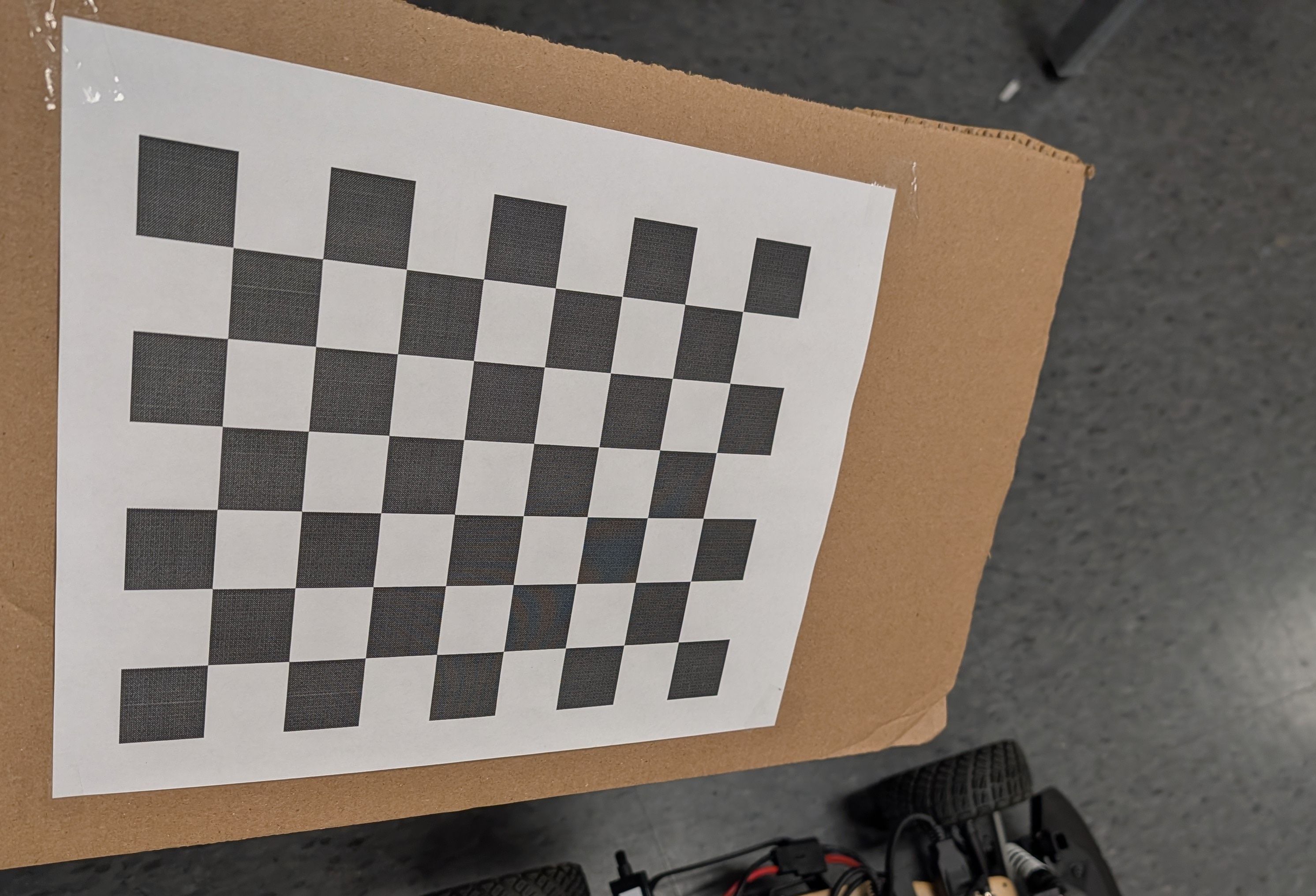
- Download the 8×6 checkerboard with 25 mm squares: Checkerboard-A4-25mm-8x6.pdf. If you generate a custom target, ensure the dimensions match the calibration script configuration.
- Print at 100% scale and secure the sheet to a rigid, flat surface such as a book or clipboard so it stays perfectly planar during data collection.
2. Launch the Calibration Session
- Power on the car and confirm the camera is connected to the desired Orin
cam0port.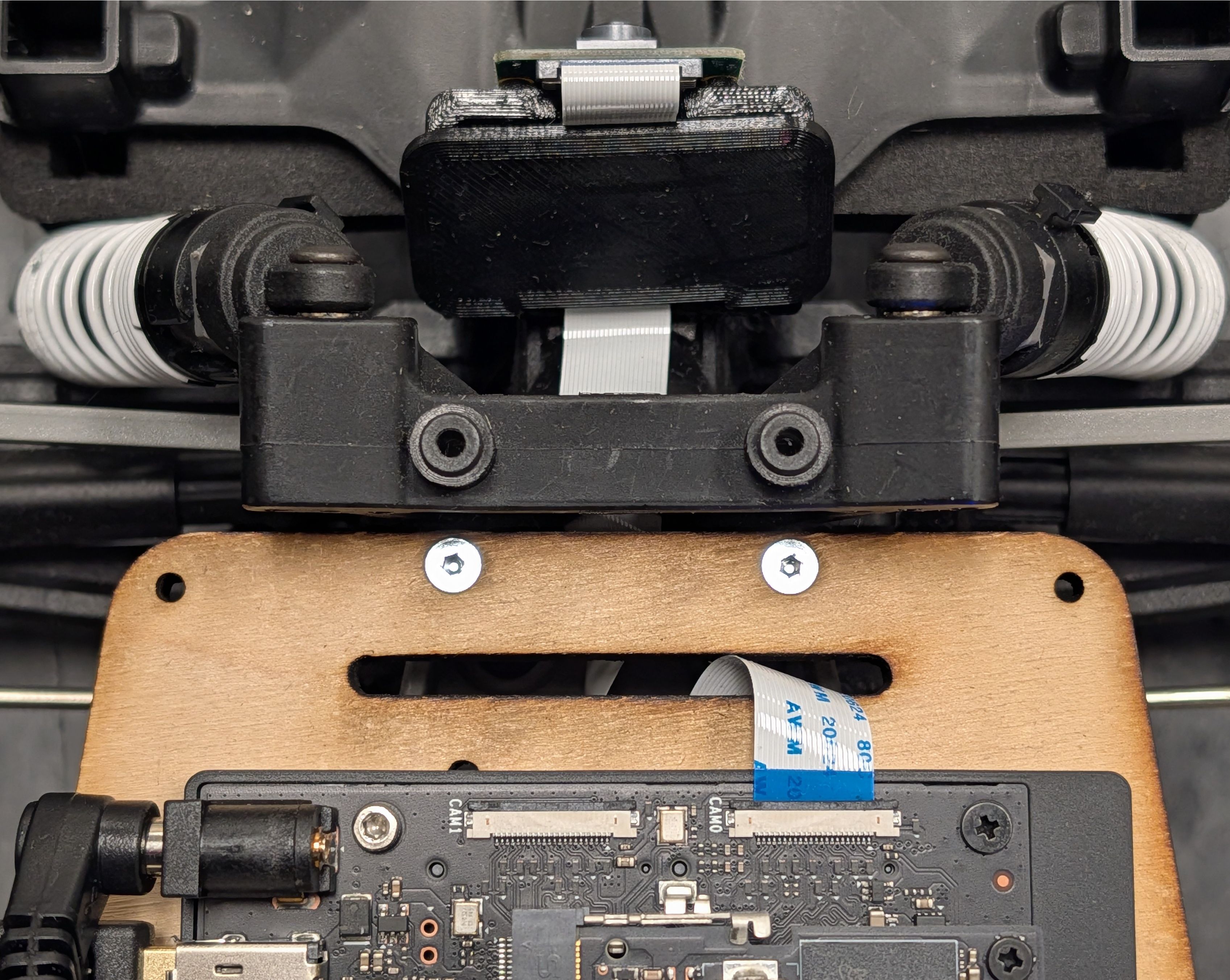
- Inside a
./container shell, start the publisher and calibration GUI using the tmuxinator profile:
cd ~/roboracer_ws/tmux/camera_calibration/
SENSOR_ID=0 tmuxinator
Use SENSOR_ID=0 for CAM0 or SENSOR_ID=1 for CAM1 to match the physical connector you are calibrating.
Wait up to 15 seconds for the camera node to initialize and start publishing images.
3. Collect Calibration Views
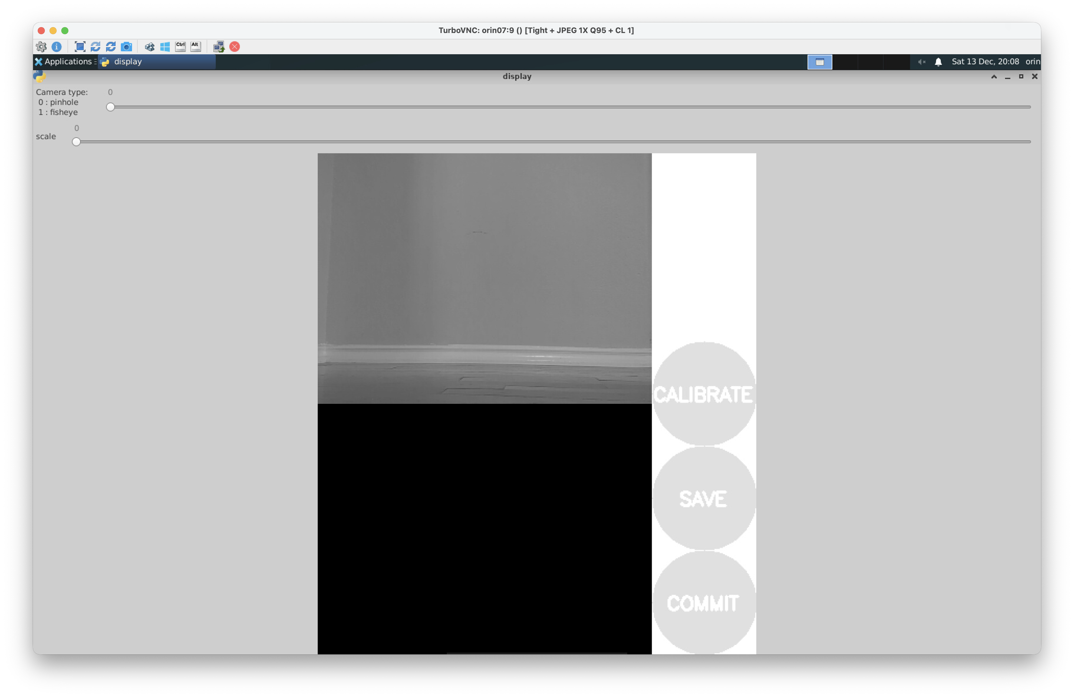
Connect to the car using TurboVNC. You should see the camera calibration GUI running:
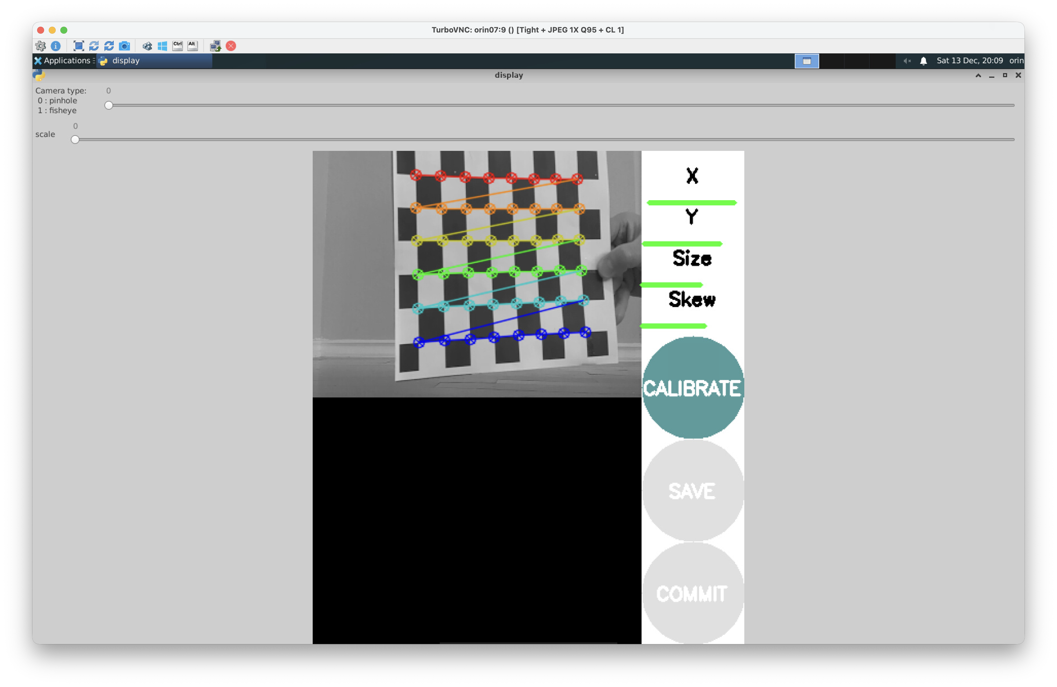
- Watch the calibration GUI and move the checkerboard across the field of view. You'll see the rainbow overlay on the checkerboard when it is being detected.
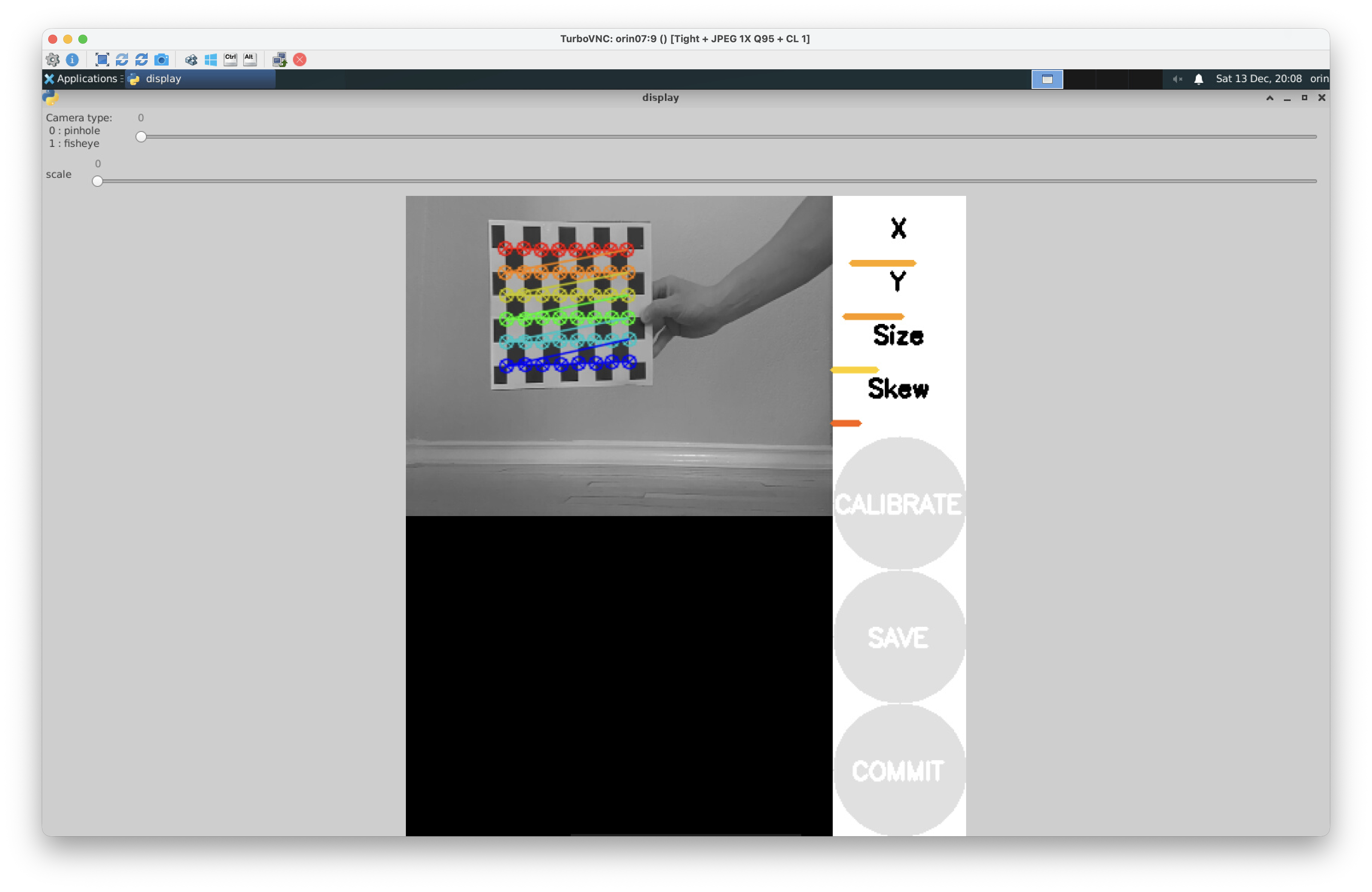
- Tilt the board, vary its distance, and reach all image corners. The calibration tool only collects data when the checkerboard is detected. If you do not see the rainbow overlay, move the checkerboard closer to the camera or tilt it until it is detected.
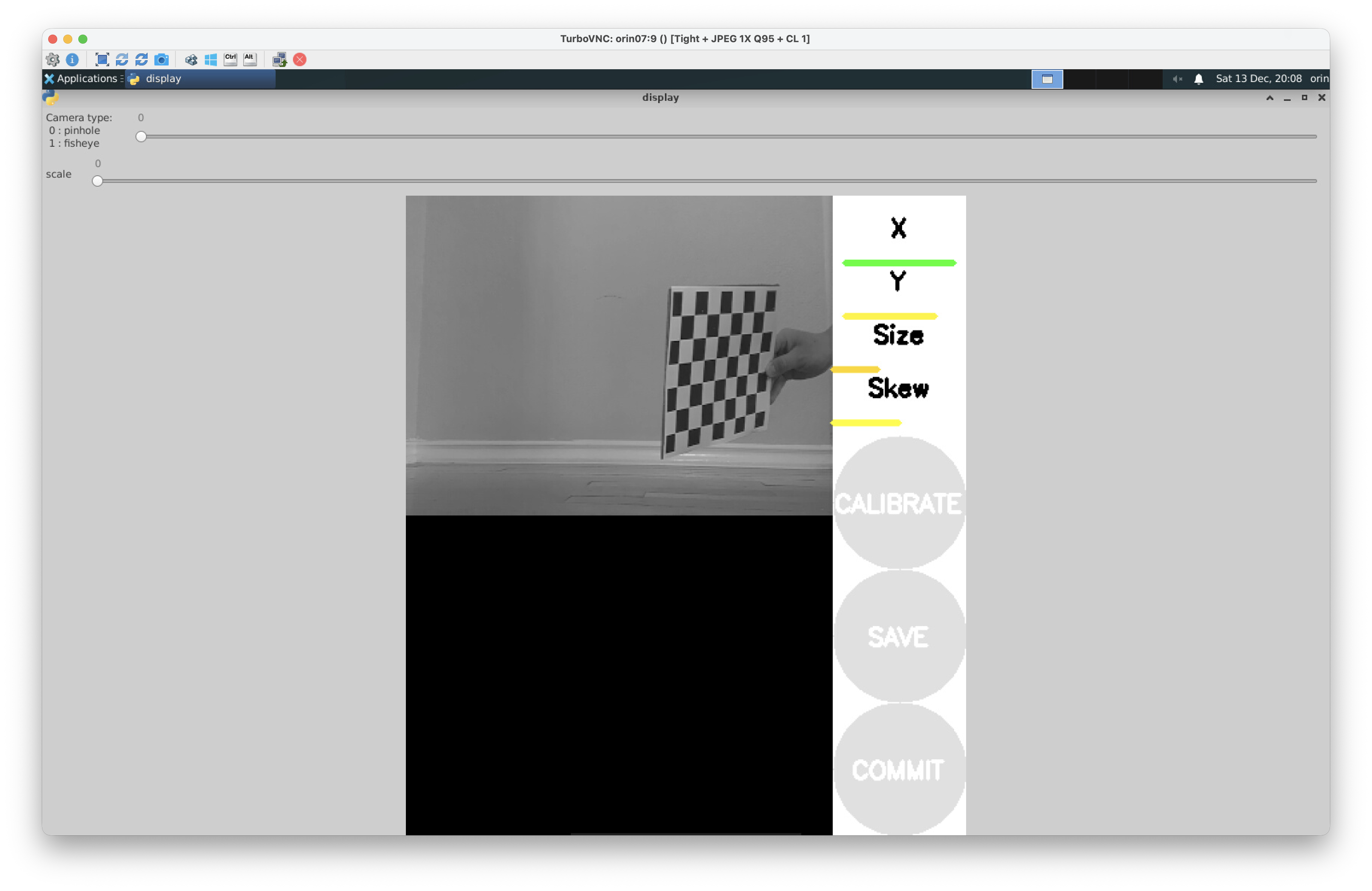 The progress bars above the Calibrate button will turn green once enough diverse samples are captured.
 - Once all the indicators turn green, stop moving the board and proceed to the next step.
Tip: Due to the position of the camera relative to the screen on the car, this step is best conducted with one team member holding and moving the calibration board while another team member monitors the calibration GUI and directs the person with the calibration board.
4. Compute and Persist Intrinsics
-
Click Calibrate and wait several minutes for the solver to finish. When the calibration is complete, you'll see output like:
mono pinhole calibration...
D = [0.10166465392228333, -0.1535165177627402, 0.022056182296122145, -0.005469796503365781, 0.0]
K = [302.2040787524777, 0.0, 157.2380561691573, 0.0, 404.0513407332305, 158.10543185171142, 0.0, 0.0, 1.0]
R = [1.0, 0.0, 0.0, 0.0, 1.0, 0.0, 0.0, 0.0, 1.0]
P = [308.6962585449219, 0.0, 155.39091561775058, 0.0, 0.0, 407.4623718261719, 161.38296729964168, 0.0, 0.0, 0.0, 1.0, 0.0]
Click Save to persist the calibration results, you'll see output such as
('Wrote calibration data to', '/tmp/calibrationdata.tar.gz'), which is where the calibration data will be saved. -
When the results appear, copy the reported matrices directly into
~/roboracer_ws/params/cameras/0/calibration.txt(or.../1/for CAM1). You will probably have to create this file. A representative output looks like:D = [0.10166465392228333, -0.1535165177627402, 0.022056182296122145, -0.005469796503365781, 0.0] K = [302.2040787524777, 0.0, 157.2380561691573, 0.0, 404.0513407332305, 158.10543185171142, 0.0, 0.0, 1.0] R = [1.0, 0.0, 0.0, 0.0, 1.0, 0.0, 0.0, 0.0, 1.0] P = [308.6962585449219, 0.0, 155.39091561775058, 0.0, 0.0, 407.4623718261719, 161.38296729964168, 0.0, 0.0, 0.0, 1.0, 0.0]
Hint: Use
vim ~/roboracer_ws/params/cameras/0/calibration.txtto create and edit the file.
Once you've created this file, you can close the calibration GUI. Press ctrl-c in the tmux pane running the calibration GUI, then exit the container shell.
5. Calibrate Additional Cameras
If you have a second camera, repeat steps 2-4 with SENSOR_ID=1 and save the output under ~/roboracer_ws/params/cameras/1/calibration.txt.
6. Camera and Lidar Extrinsics
Now that you've completed the camera intrinsic calibration, we will review the extrinsic calibration between the lidar and camera frames. The intrinsic calibration parameters describe the internal properties of the camera, while the extrinsic calibration defines the rigid body transform between the lidar and camera frames. Perfoming both calibrations allows us to accurately project lidar points into the camera image plane. Because the LIDAR and camera are rigidly mounted to the roboracer chassis, this information is published as a static transform in ROS.
The extrinsic calibration between the lidar and camera frames has already been measured for you. This transformation is then specified in the roboracer's robot description package.
To publish the transforms described by the roboracer_description package, launch the following:
ros2 launch roboracer_description description.launch.py
Note: The command above to launch the robot description package for the roboracer is automatically launched in many tmuxinator configurations.
7. Project Lidar into the Image
- Now that you have created the camera calibration file you can launch the teleoperation tmuxinator profile to start the camera, lidar, and teleop nodes:
cd ~/roboracer_ws/tmux/teleop/
tmuxinator
- Open Foxglove Studio on your laptop and connect to your car.
- Adjust the panels as follows:
- Ensure the Image panel is subscribing to
/camera_0/image_rect/compressedtopic to view the undistorted camera feed.You should notice the edges around the camera are no longer straight. This is because the internal distortion of the camera has been corrected and the pixels moved appropriately to project the image correctly onto the image plane.
- With the Image panel selected, enabled the
/scantopic by clicking the eye icon next to it in the topic list (left side). - Increase the
/scanmarker size until the points are visible. - Now you should be able to see the lidar points projected onto the undistorted camera image (shown on the right view).
- For debugging, it may also be useful to enable the camera view in the 3D panel to see the camera image projected into 3D space relative to the camera frame (shown on the middle view).
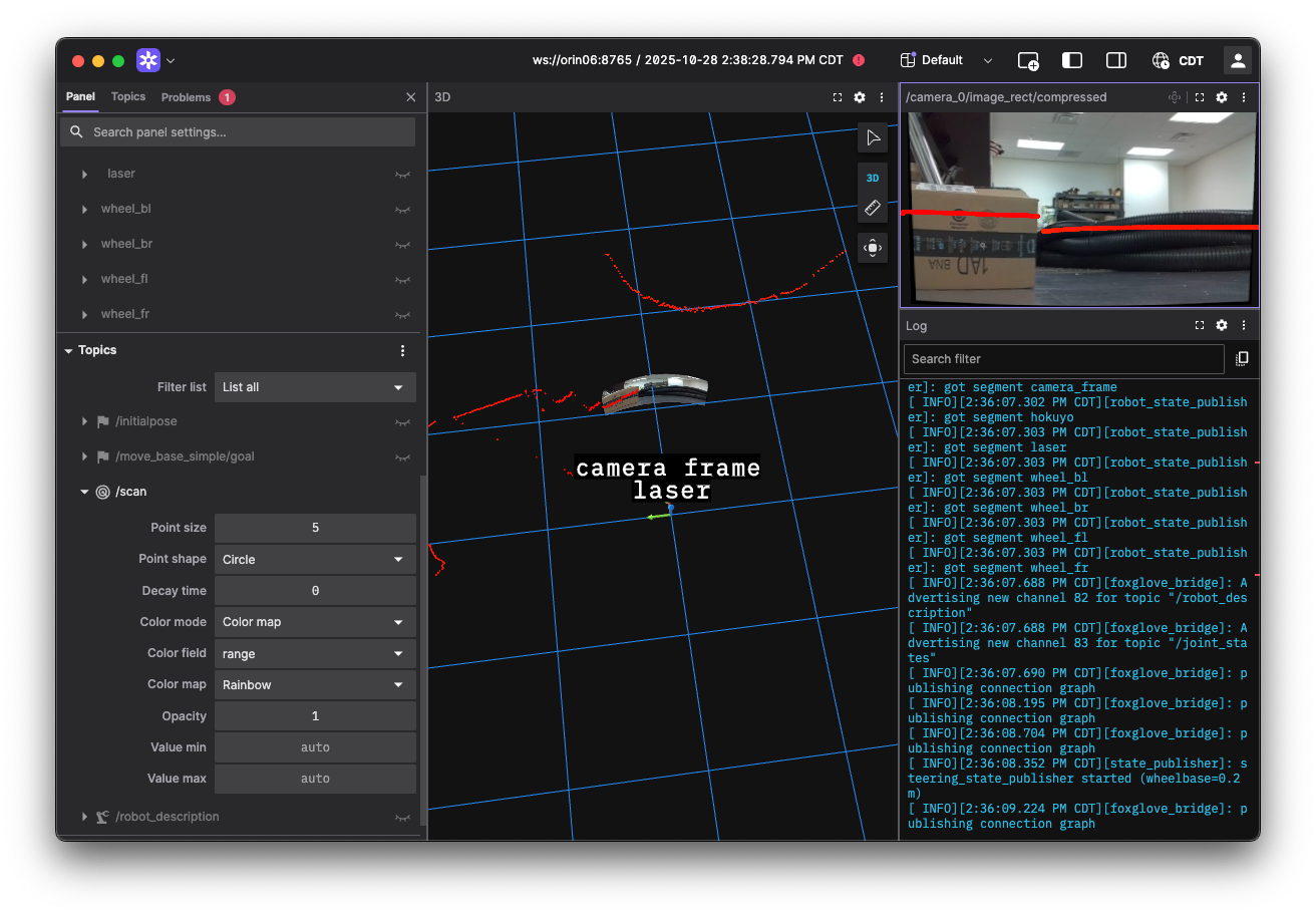
- Ensure the Image panel is subscribing to
Lab Notebook
Take a screenshot showing the projected lidar points overlaid on the rectified camera images in your lab notebook titled "Lidar Points Projected onto Camera Image".