Platform Assembly
This guide describes the complete assembly process for the UT AMRL RoboRacer autonomous vehicle platform. By the end of this guide, you will have a fully assembled 1/10th scale autonomous car equipped with a BLDC motor, VESC motor controller, Jetson Orin Nano, Hokuyo LiDAR, IMU, Raspberry Pi camera, and a mounted display.
These steps have been completed for you
Prior to the FRI course, these steps have been completed for you, but are included here for completeness.
Estimated Assembly Time: 2–3 hours
STL Files for laser cut and 3D Print
TODO: Download links for plate, lidar top, lidar bottom, usb hub clamps, pi camera adapter and lid
Required Tools
- Soldering iron and solder
- M2.5, M3, and M5 Allen key set
- M3 and M5 tap and tap handle
- Wire strippers
- Heat shrink tubing and heat gun
- Phillips screwdriver
Safety Precautions
- LiPo batteries are a fire hazard if punctured or short-circuited. Always disconnect the battery before working on wiring.
- Soldering should be performed in a well-ventilated area. Avoid contact with the iron tip and hot joints.
- High-current connectors (TRX, bullet connectors) can arc if shorted. Double-check polarity before making any power connections.
Flashing VESC & Flashing Orin
Chassis and Motor
Step 1: Remove the Body Shell
Remove the body shell off the chassis and lift the shell off the car. Set it aside, it will not be reinstalled.
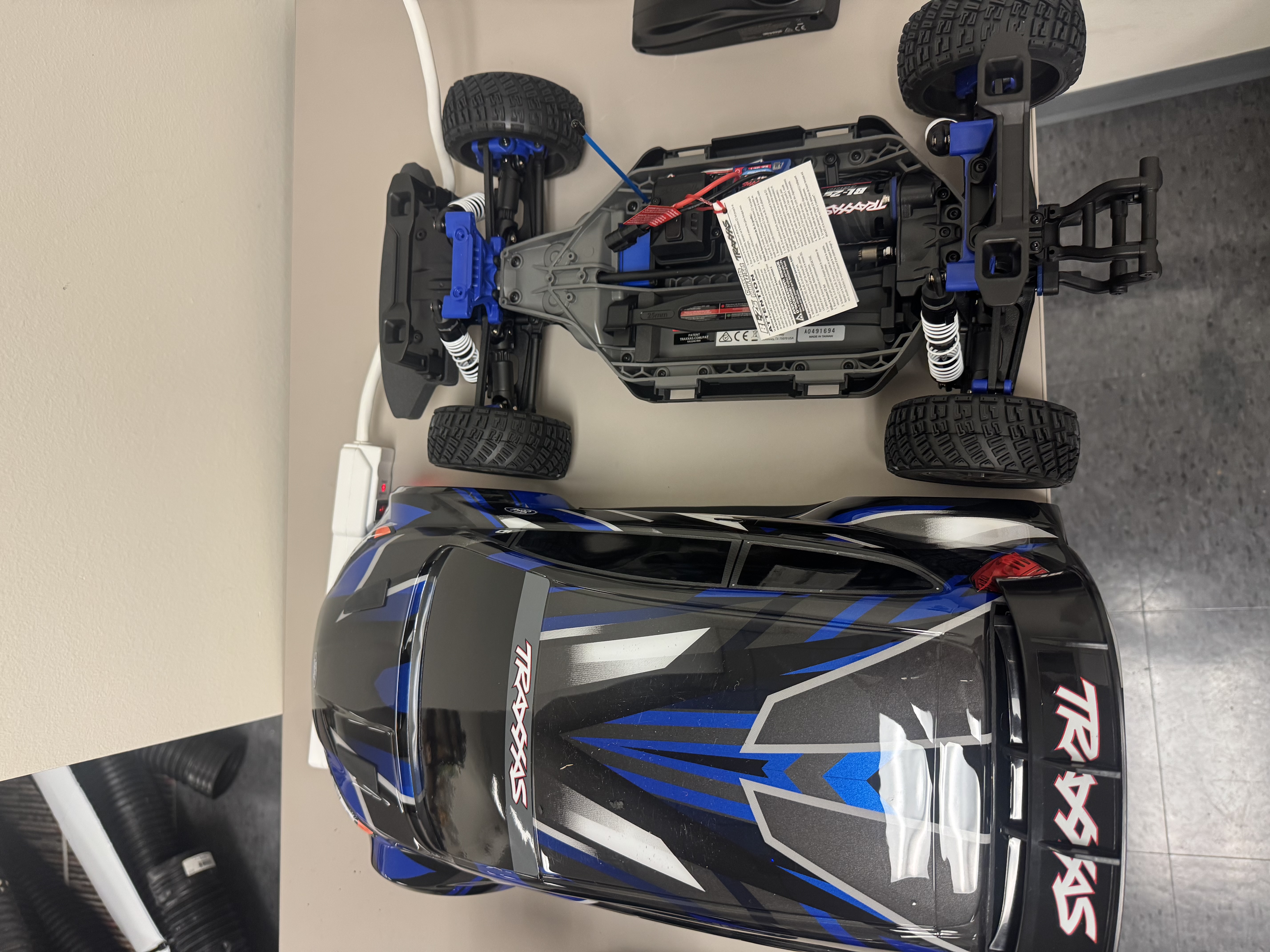 Figure 1: Body shell removed to expose the chassis.
Step 2: Strip the Chassis
Remove all stock components from the chassis. Complete the following steps in order:
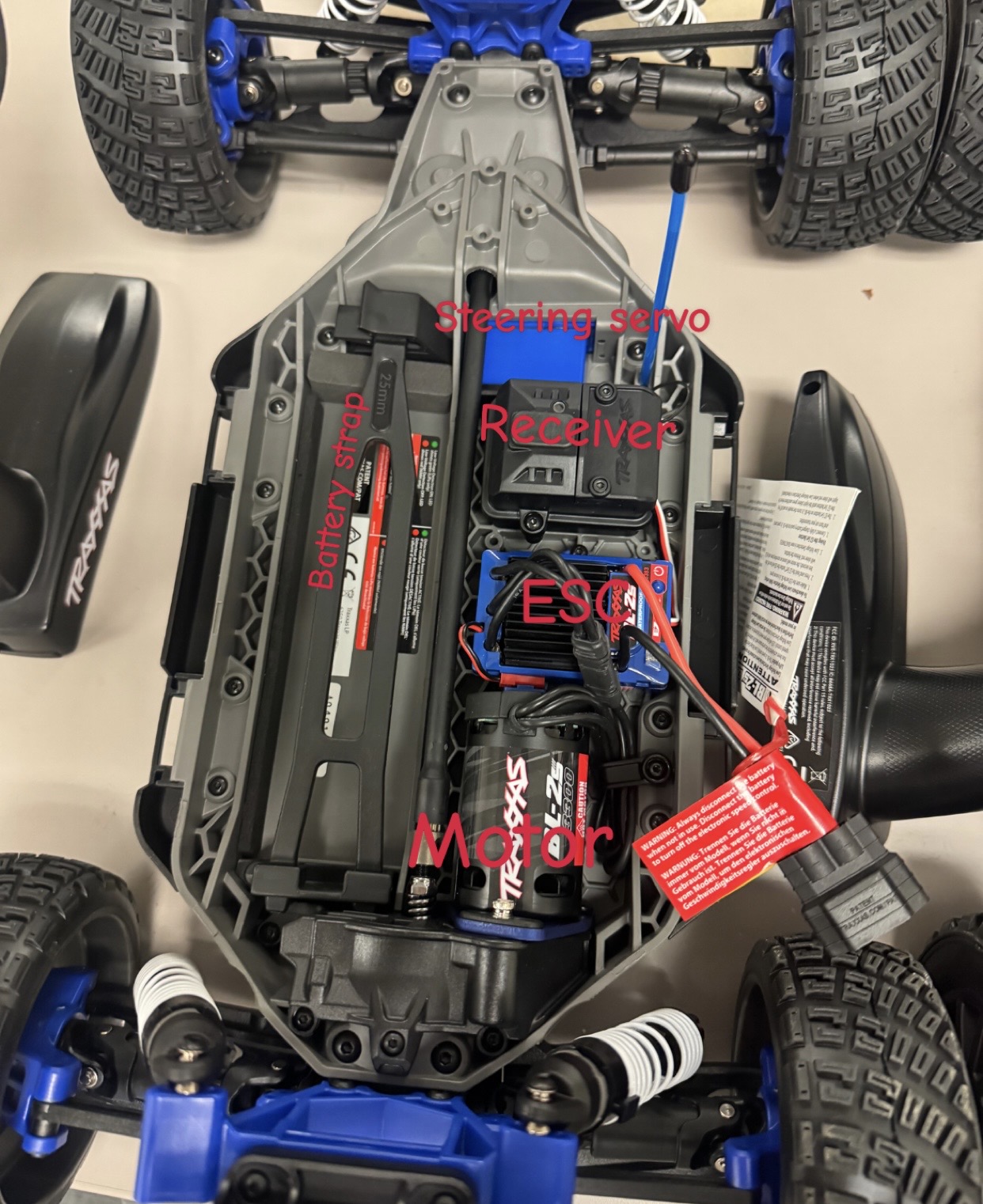
- Remove the battery strap by pulling up on the pin.
- Remove the motor cable clip by unscrewing its screw.
- Remove the TRAXXAS ESC by unscrewing the screws on its side.
- Unscrew the antenna by removing the small screw to its side.
- Remove the TRAXXAS receiver lid by unscrewing the screws on its top.
- Disconnect all pins connected to the receiver.
- Remove the receiver from its case by pulling it out. It is glued in, so you can use the screwdriver to pry it out.
- Remove the receiver case by unscrewing the screws that were on its bottom.
- Remove the stock motor by unscrewing the screw on the motor mount. Keep the motor mount and screw, they will be reused.
Leave the steering servo installed.
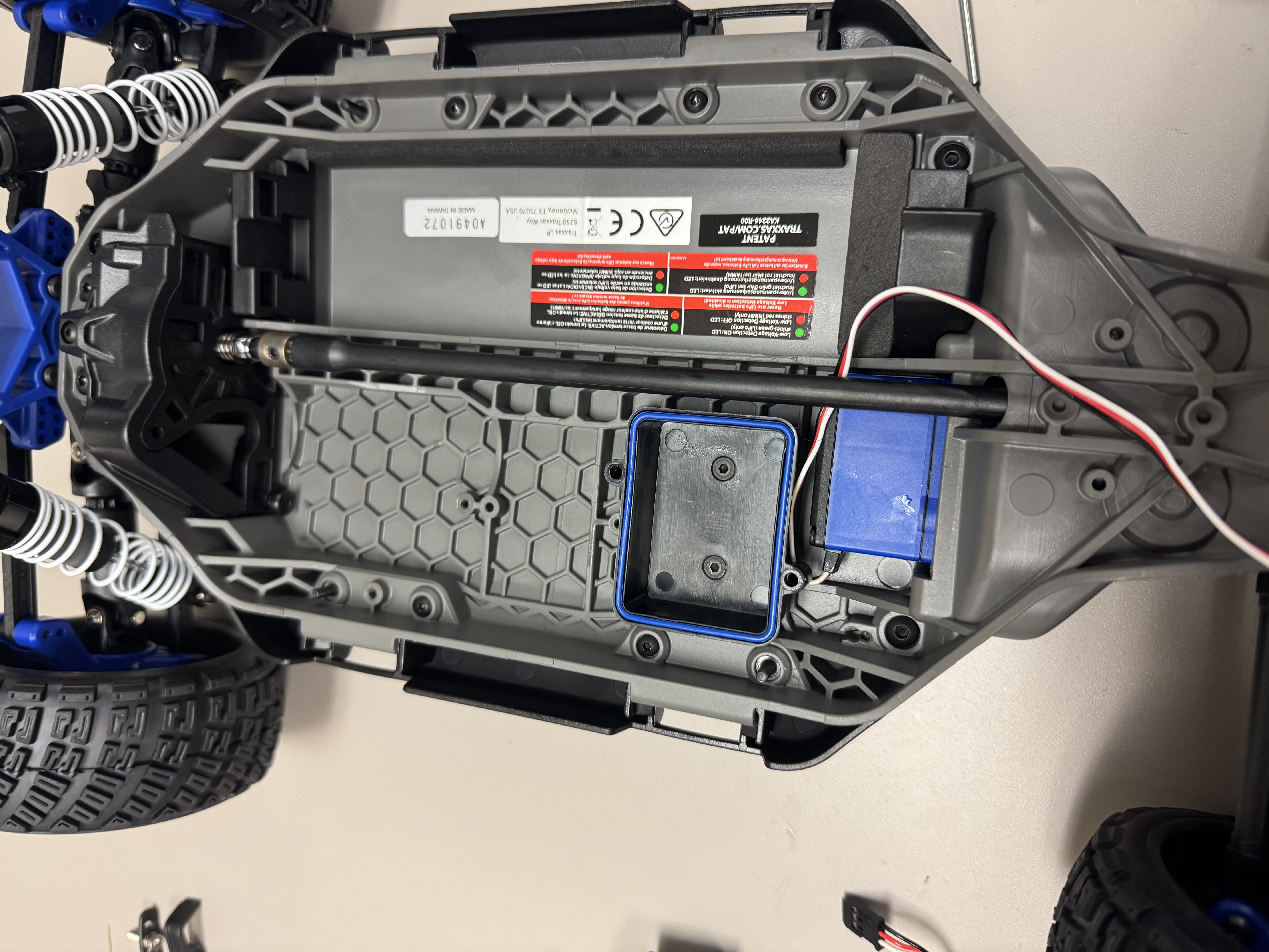
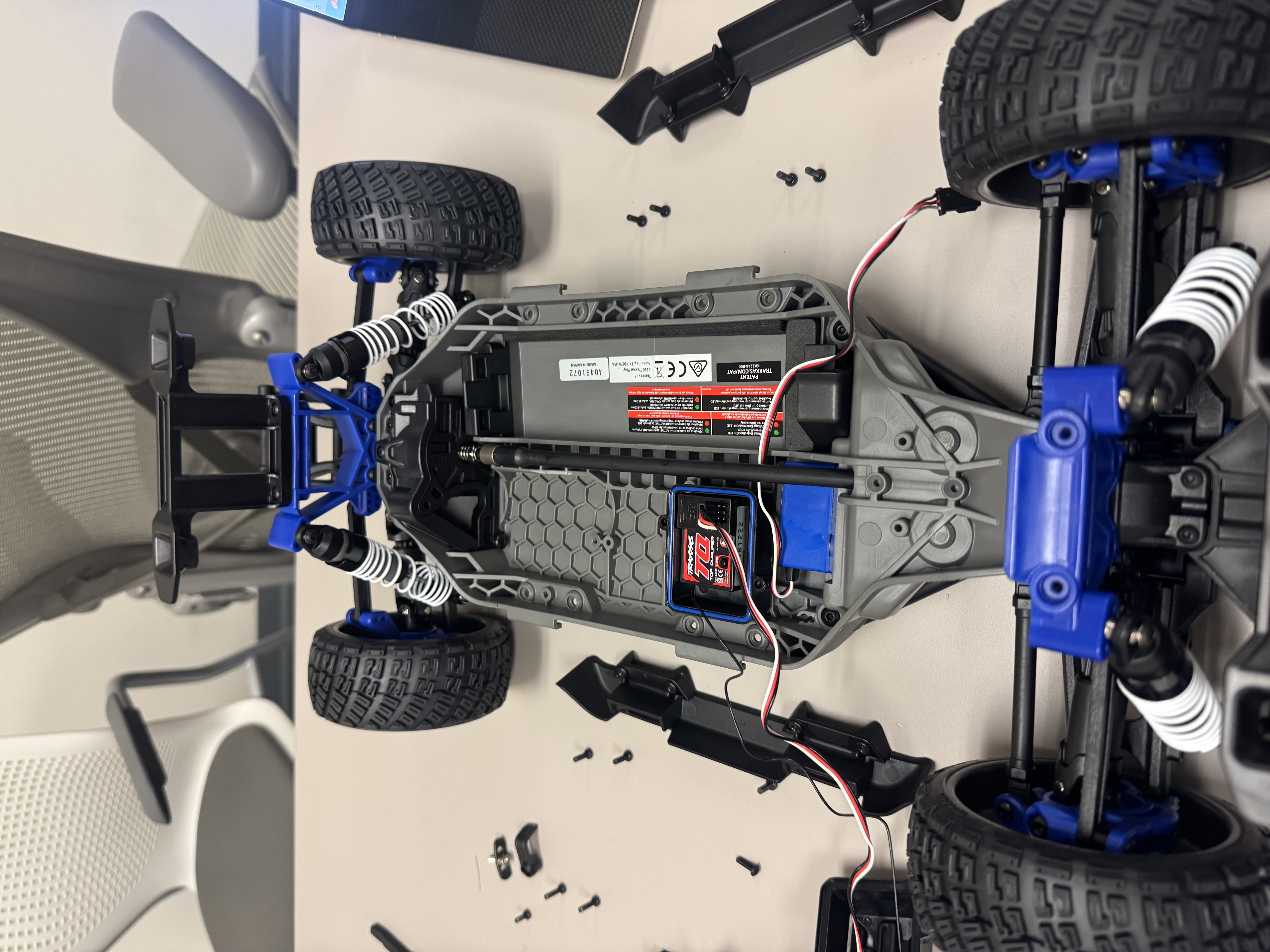 Figure 2: Chassis after all stock components have been removed.
Step 3: Mount the Motor
- Remove the gear from the stock motor and place it on the new motor at the same position it was on the old one, about 3mm from the stem.
- Attach the new motor to the chassis using the same mount and screw, ensuring the motor is attached to the mount at the same position as shown below.
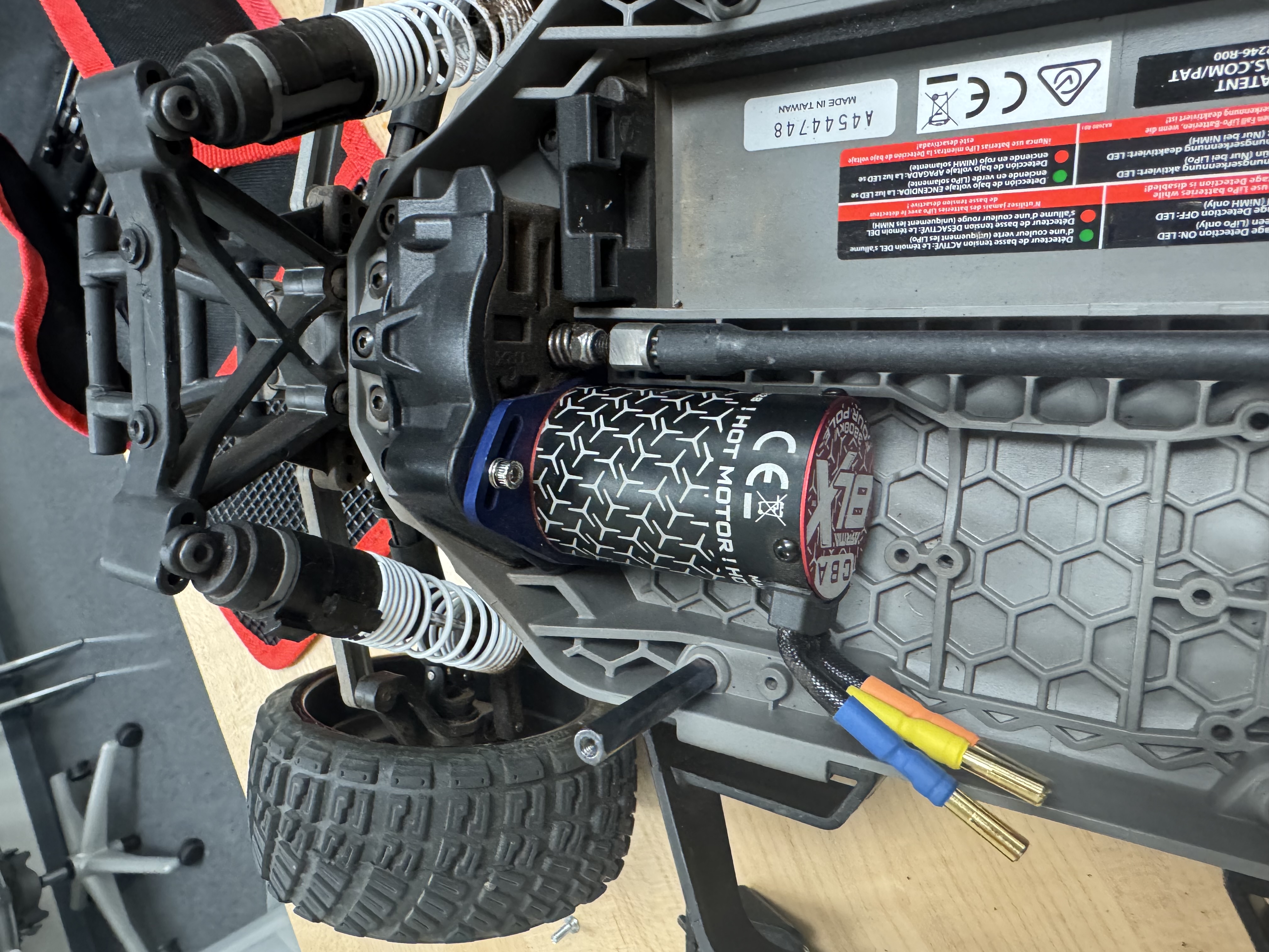 Figure 3: BLDC motor mounted to the chassis.
Step 4: Install Standoff Mounting Screws
Flip the screws on the chassis at each standoff location, as shown below.
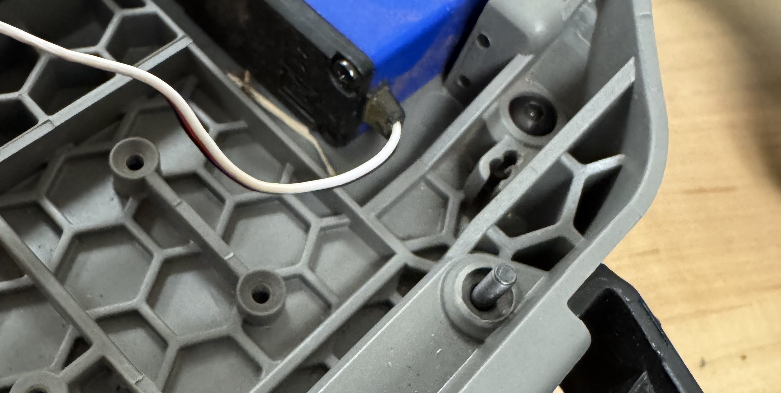 Figure 4: Orientation of the flipped M3 x 10 mm screws
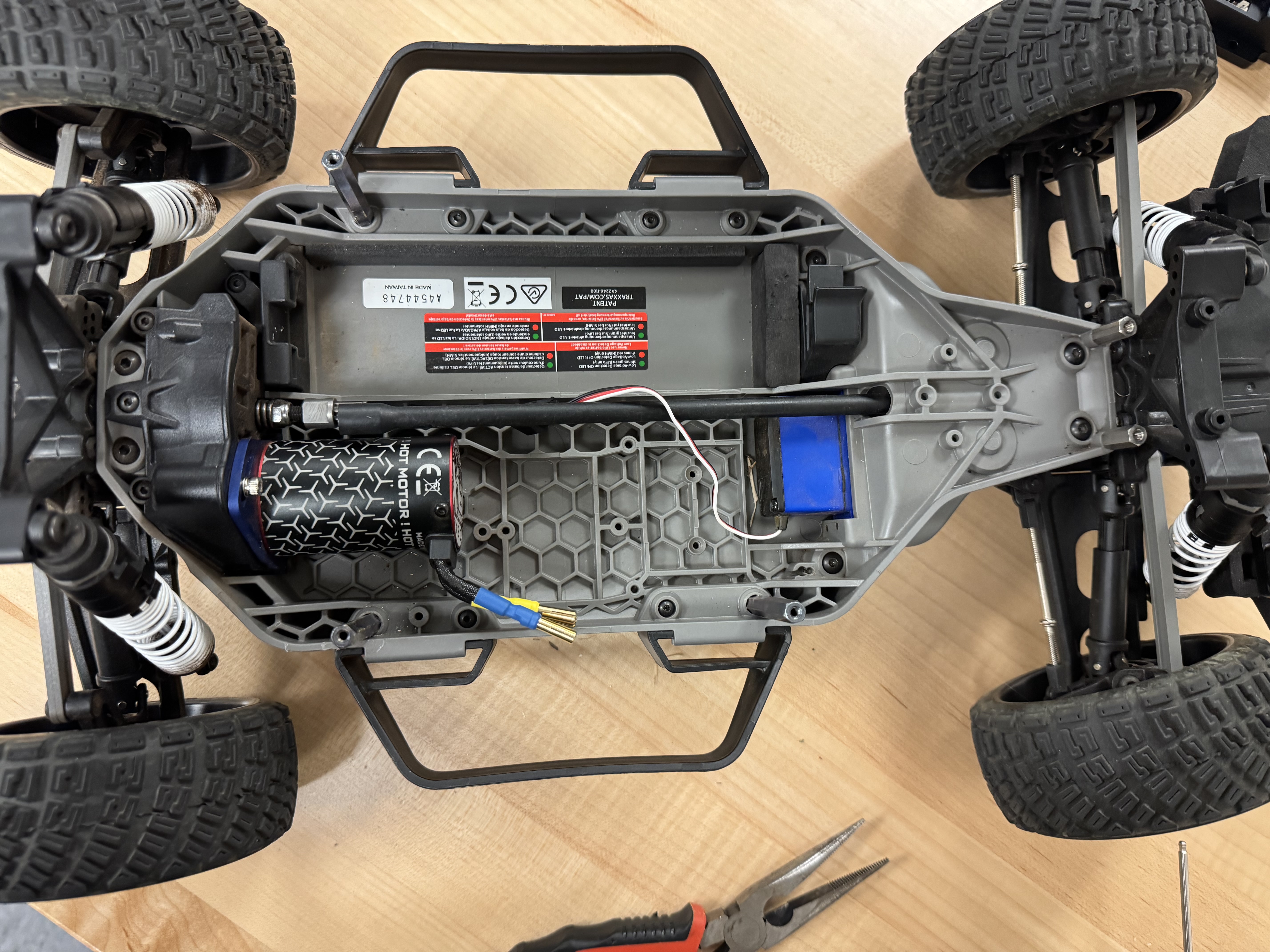 Figure 5: Standoff placement
Step 5: Attach Standoffs
Screw in M3 x 45mm x 6mm female-female standoffs in the location of the flipped screws above (corners of the middle of the chassis), and two M3 x 14 mm x 5 mm male-female standoffs seen at the bottom of figure 5.
VESC Motor Controller
Remove the protective wrapping from the VESC before beginning assembly.
Step 1: Solder Bullet Connectors
On the three wires extending from the MOSFETs on the VESC, solder 4 mm female gold bullet connectors (C131-20) to the opposite ends. Apply heat shrink tubing over each solder joint.
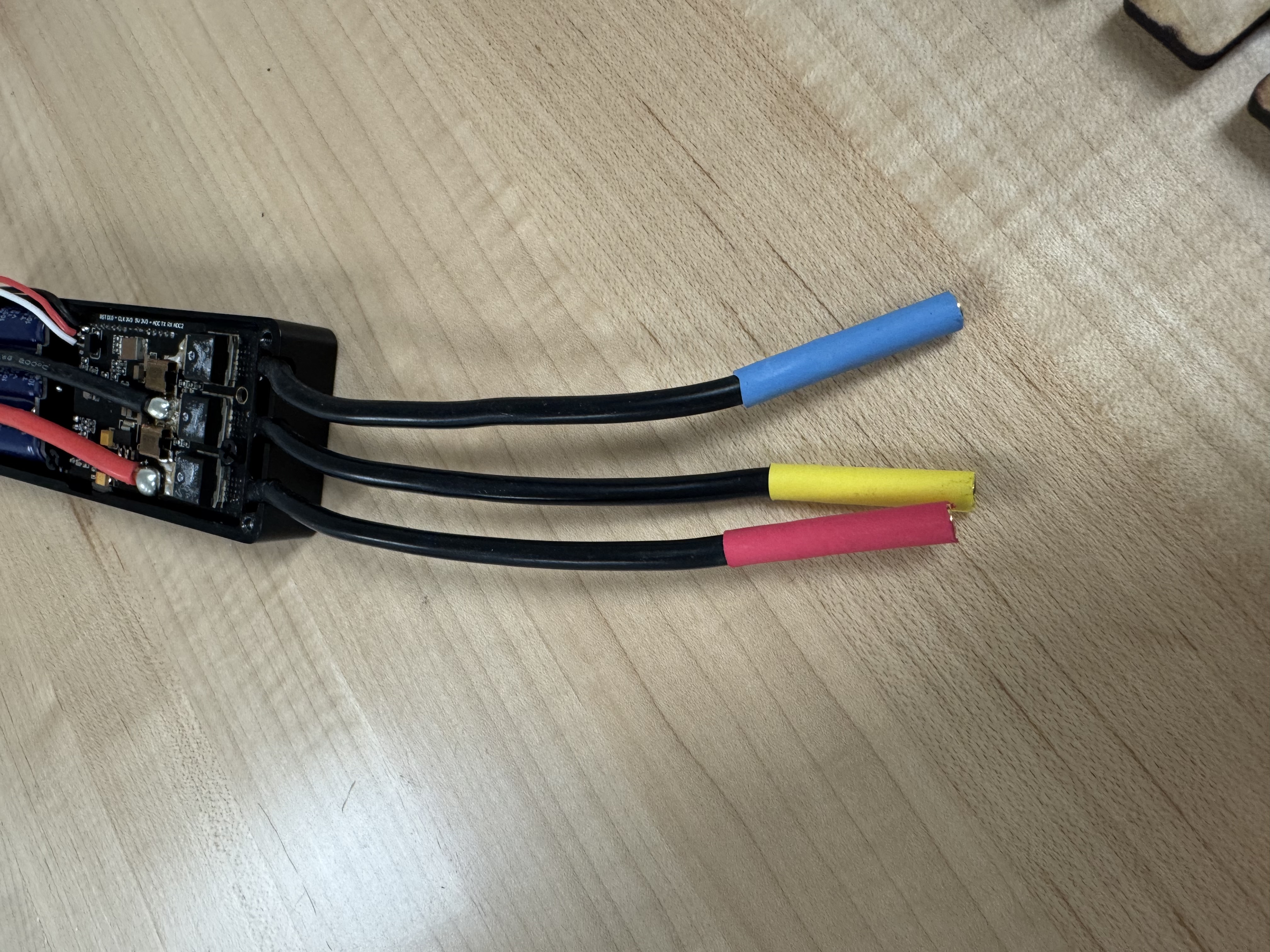 Figure 6: 4 mm female gold bullet connectors soldered to VESC motor output wires.
Step 2: Solder TRX Connectors
Solder the two remaining power wires on the opposite side of the VESC to female TRX connectors. Refer to this TRX connector soldering demonstration for guidance.
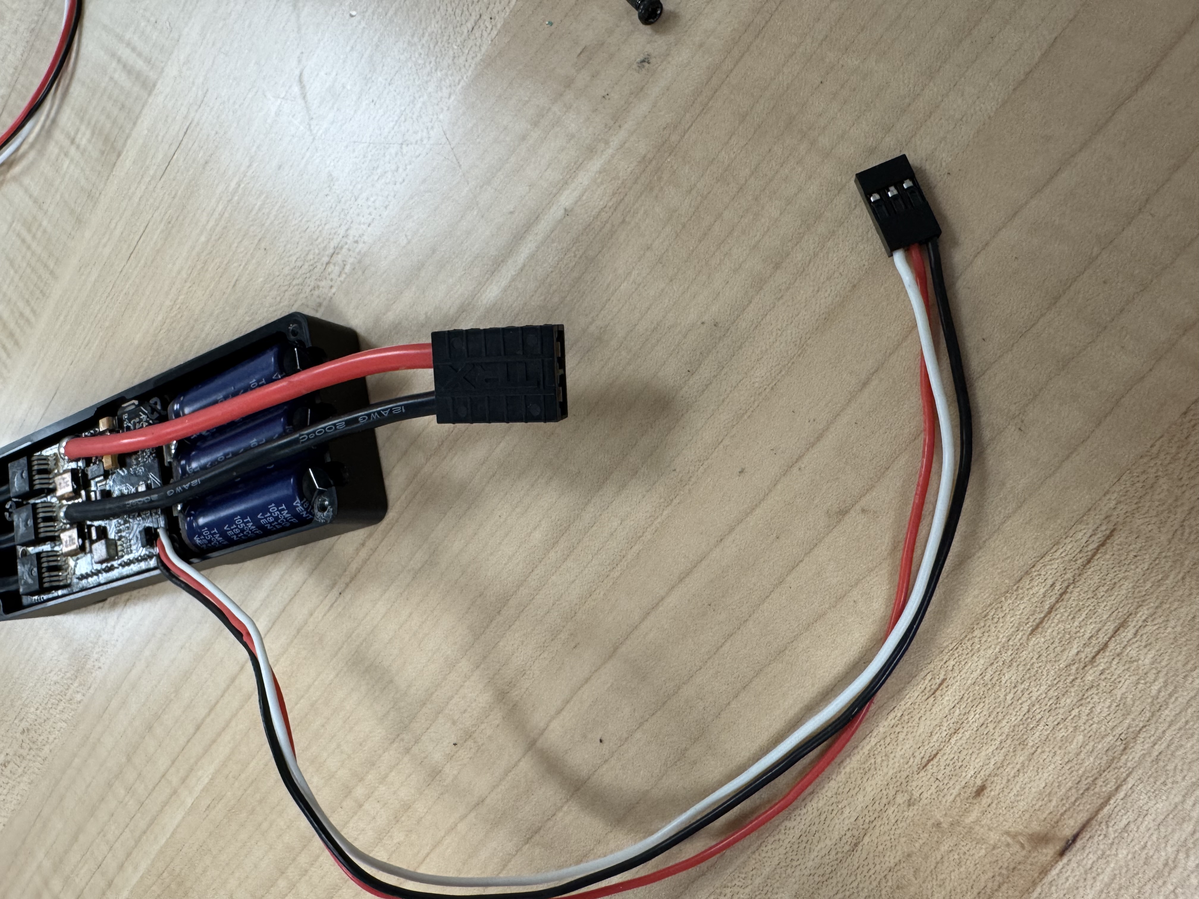 Figure 7: Female TRX connectors soldered to VESC power input wires.
Step 3: Install JST Connector
TODO: Solder a JST-SM 3-pin connector onto the remaining cables from the VESC.
Step 4: Prepare the Motor Controller Case
Remove all inner and outer screws from the motor controller case.
Step 5: Seat the VESC in the Case
Insert the VESC into the case, ensuring that the MOSFETs rest flat on the thermal cushions inside the enclosure.
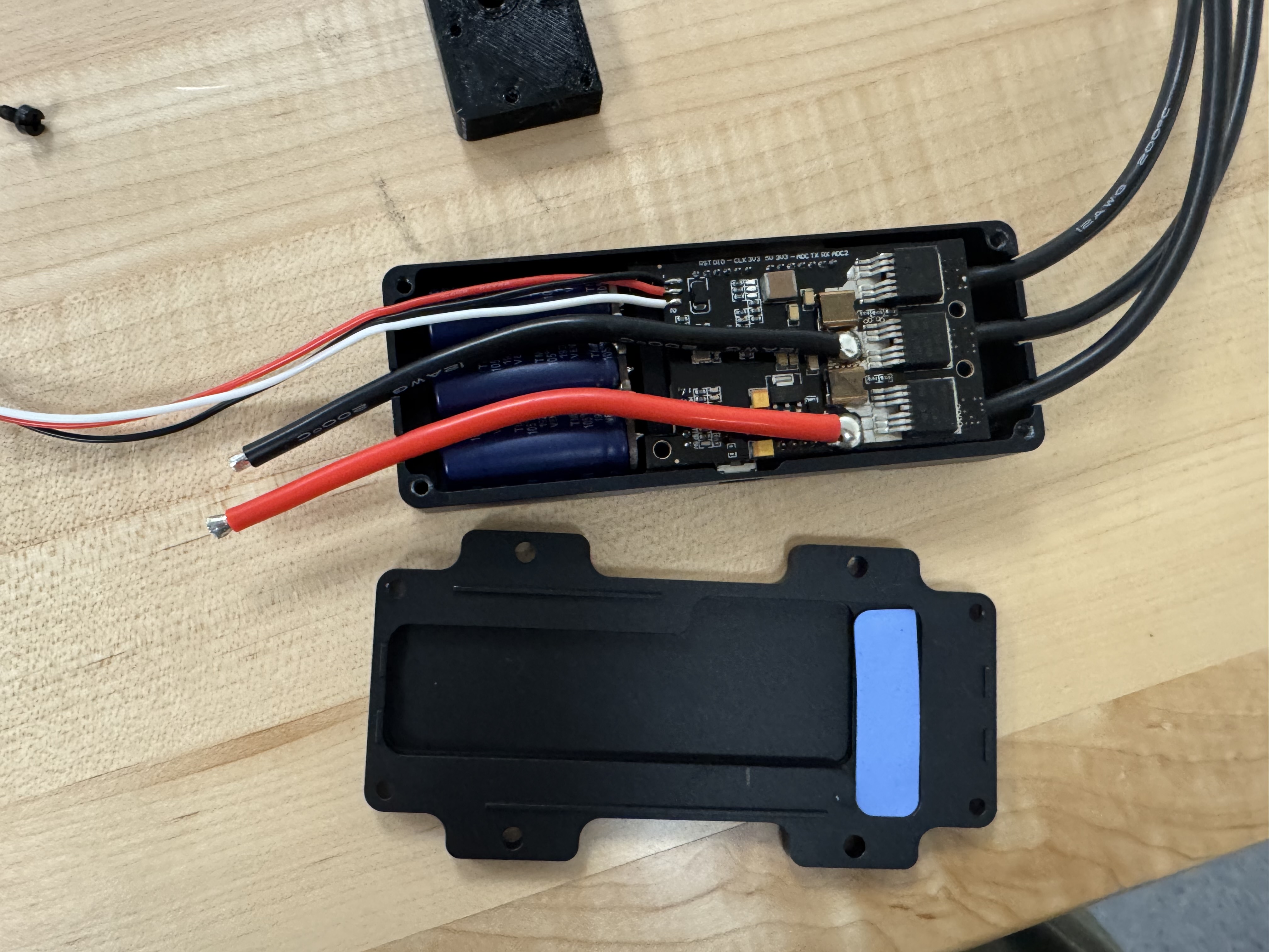 Figure 8: VESC seated inside the motor controller case with MOSFETs resting on thermal cushions.
Step 6: Secure the VESC
Fasten the VESC to the case using the provided M3 × 8 mm screws on the inner mounting holes. Take care not to pinch any wires. Then attach the case cover using the provided M3 × 8 mm screws on the outer holes.
Step 7: Connect the USB Cable
Plug the Mini-USB end of a Mini-USB to USB cable into the VESC.
Step 8: Mount the Controller to the Plate
Tap the four outermost holes on the motor controller case for M5 screws. Countersink the wooden plate for an M5 flat head on the other side of the wooden plate, where it will be screwed, as shown in the picture. Secure the motor controller to the wooden mounting plate using M5 x 0.8mm × 12 mm flat head screws.
Your bottom plate assembly should now look like this:
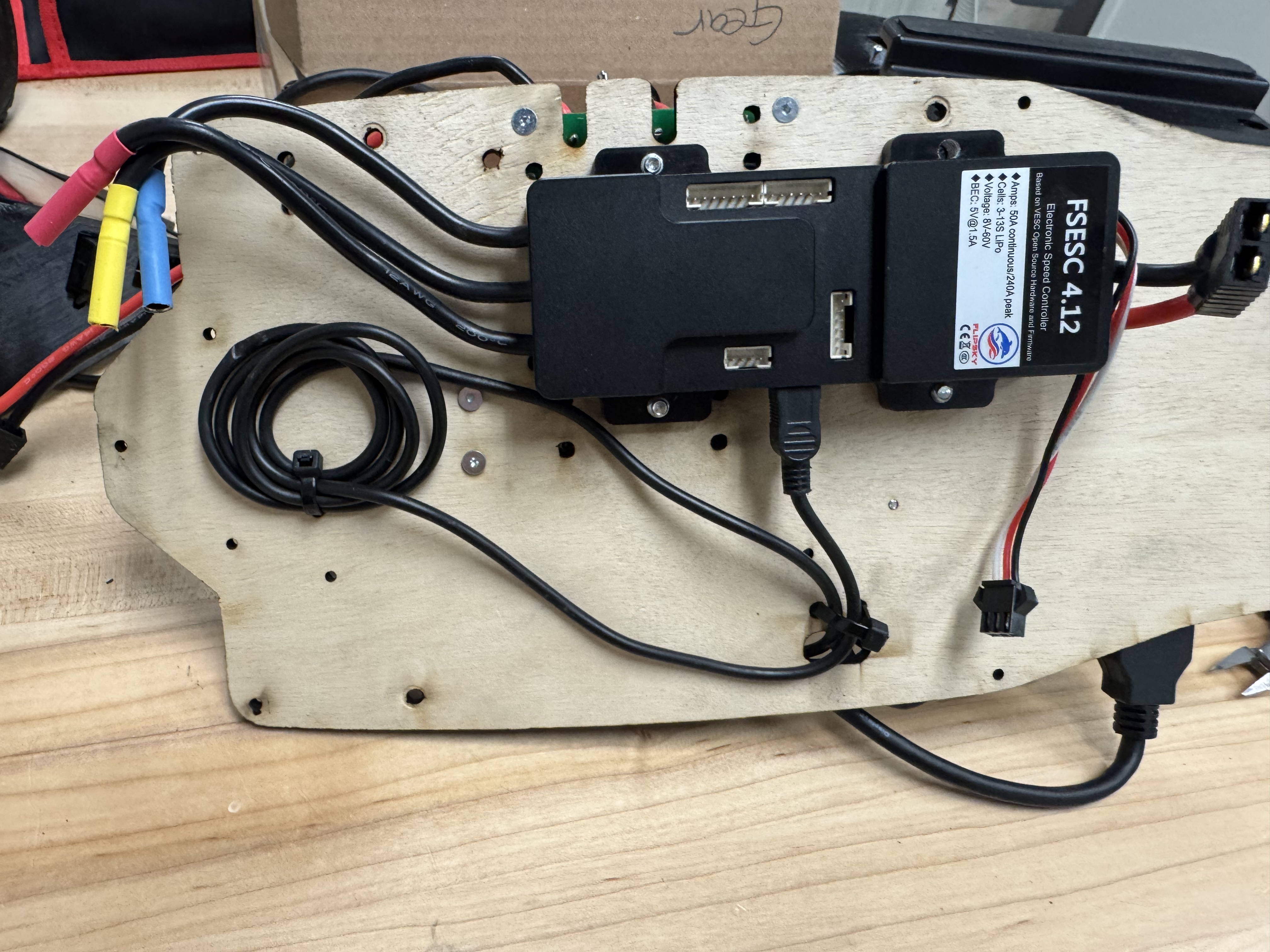 Figure 9: VESC motor controller mounted to the bottom plate.
Wiring
Step 1: Prepare the LiDAR Power Cable
On the Hokuyo LiDAR's 6-pin JST connector cable, remove all wires except the brown (12V) and blue (GND) leads. Strip the wire ends and connect them to the corresponding terminals on the power board, in the screw terminal block labeled LiDAR.
Step 2: Prepare the Jetson Power Cable
Strip the leads of a 2.5 mm × 5.5 mm DC barrel jack pigtail and connect them to the corresponding terminals on the power board (white striped wire +), in the screw terminal block labeled JETSON.
Step 3: Prepare Battery and VESC Power Cables
Create two 14 AWG pigtails with male TRX connectors, one about double the length of the other (refer to the soldering demonstration linked above). Connect them to the corresponding terminals on the power board, in the screw terminal blocks labeled BAT and VESC.
Your completed power board wiring should look like the following:
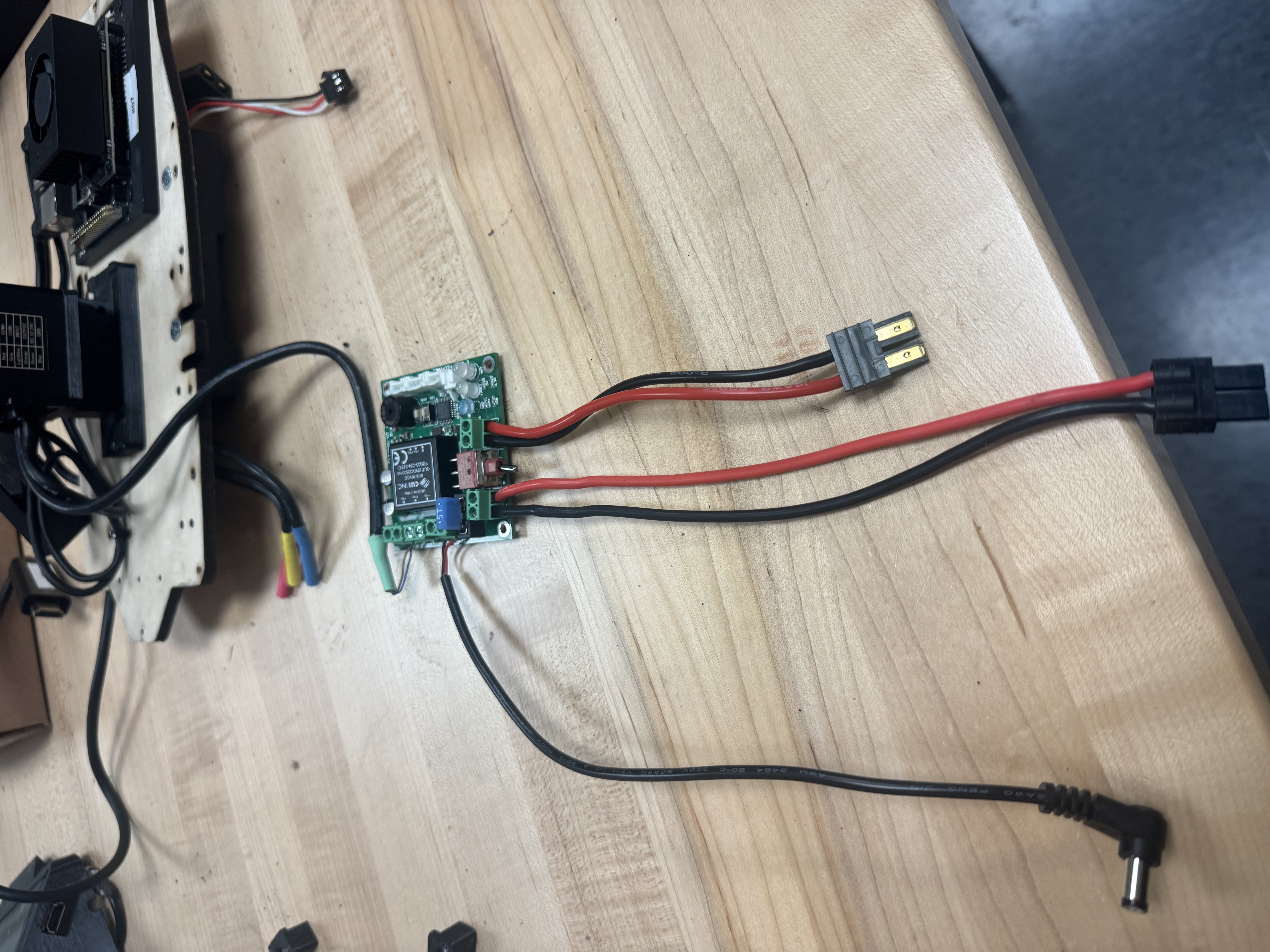 Figure 10: Completed power board wiring (front view).
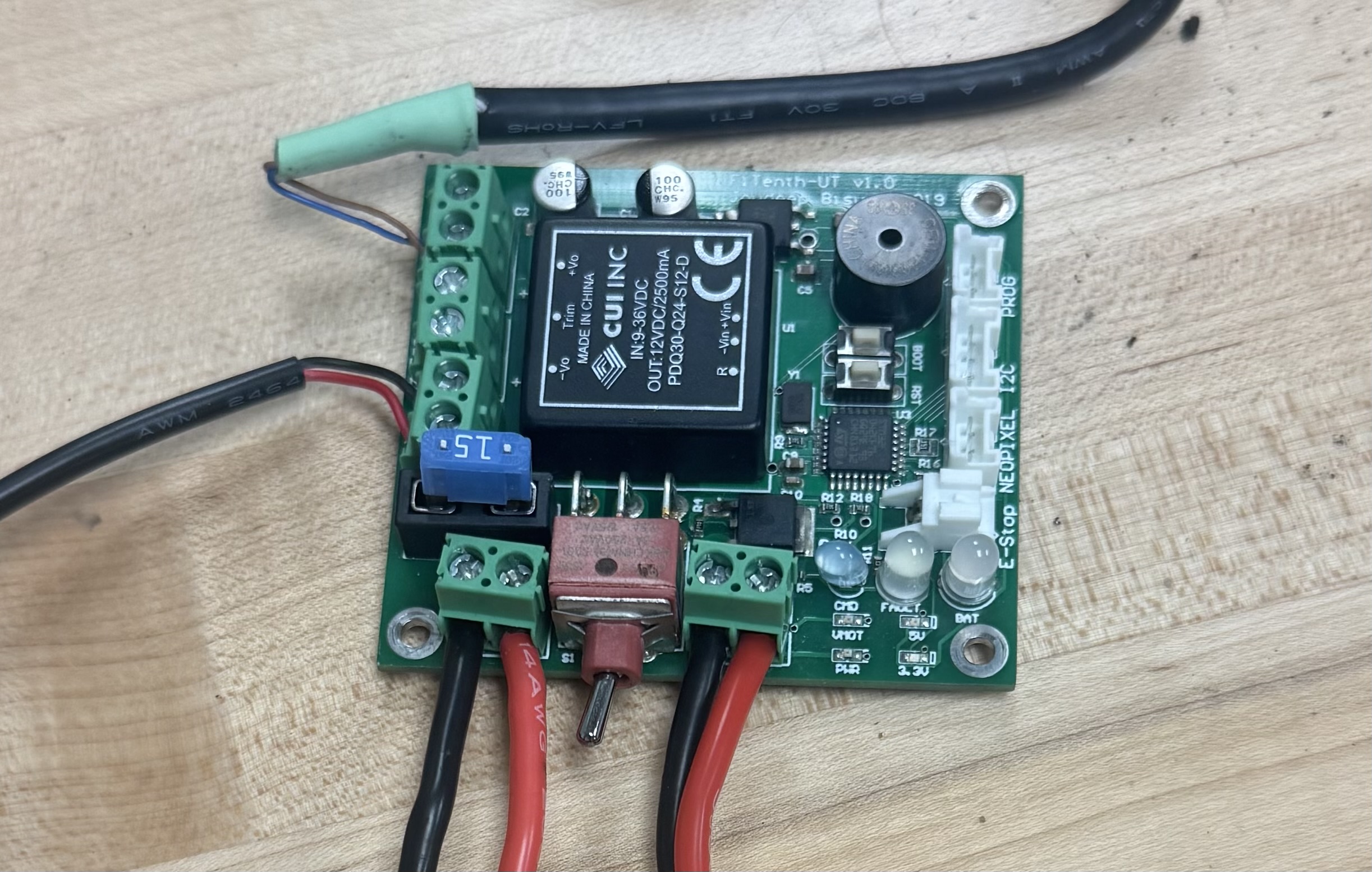 Figure 11: Completed power board wiring (complete view).
Mounting
Step 1: Prepare the LiDAR Mount
Tap the two corner holes on the Hokuyo LiDAR with an M3 tap. Attach the 3D-printed LiDAR adapter piece using M3 x .5mm × 10 mm flat head screws.
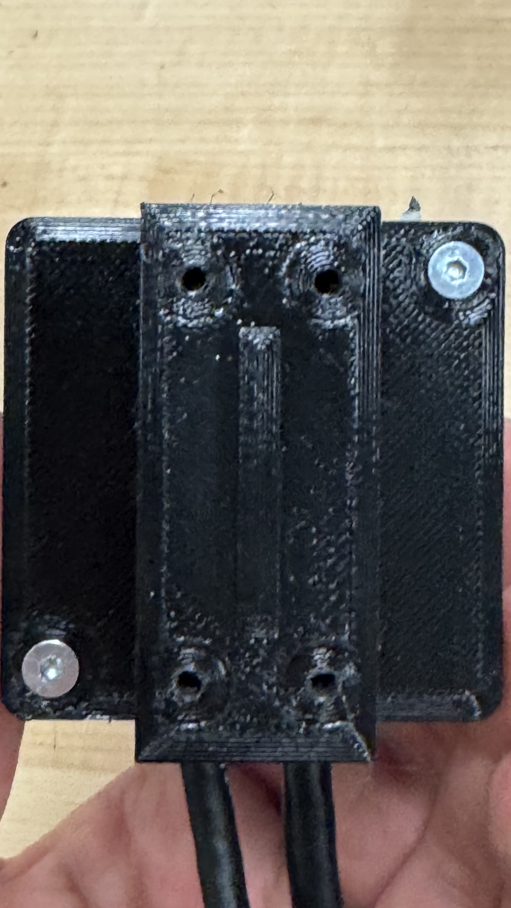 Figure 12: 3D-printed adapter attached to the LiDAR.
Step 2: Assemble the LiDAR Mount Base
Screw the 3D-printed adapter piece to the LiDAR adapter using four M3 × .5mm x 10 mm flat head screws.
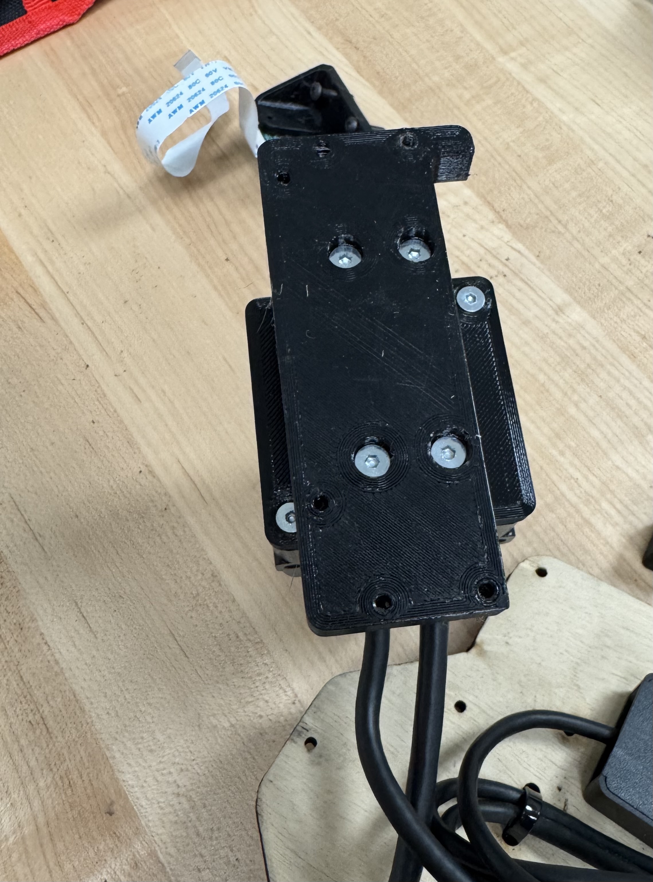 Figure 13: LiDAR adapter assembled with base mount.
Step 3: Attach the LiDAR Assembly to the Plate
Secure the assembled LiDAR mount to the mounting plate using M3 x .5mm x 10mm flat head screws from the bottom.
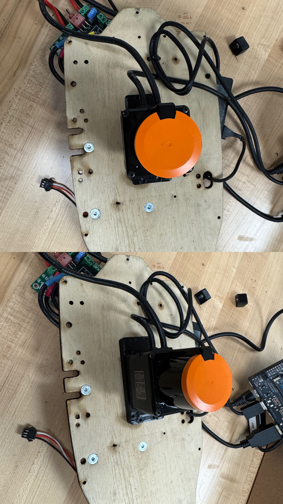 Figure 14: LiDAR assembly mounted to the plate.
Step 4: Mount the Jetson Orin Nano
Using a 2/32 drill bit, drill through the plate at the three Orin mounting positions. To locate each hole, find the silver screws tip protruding from the corners of the Orin from figure 15.
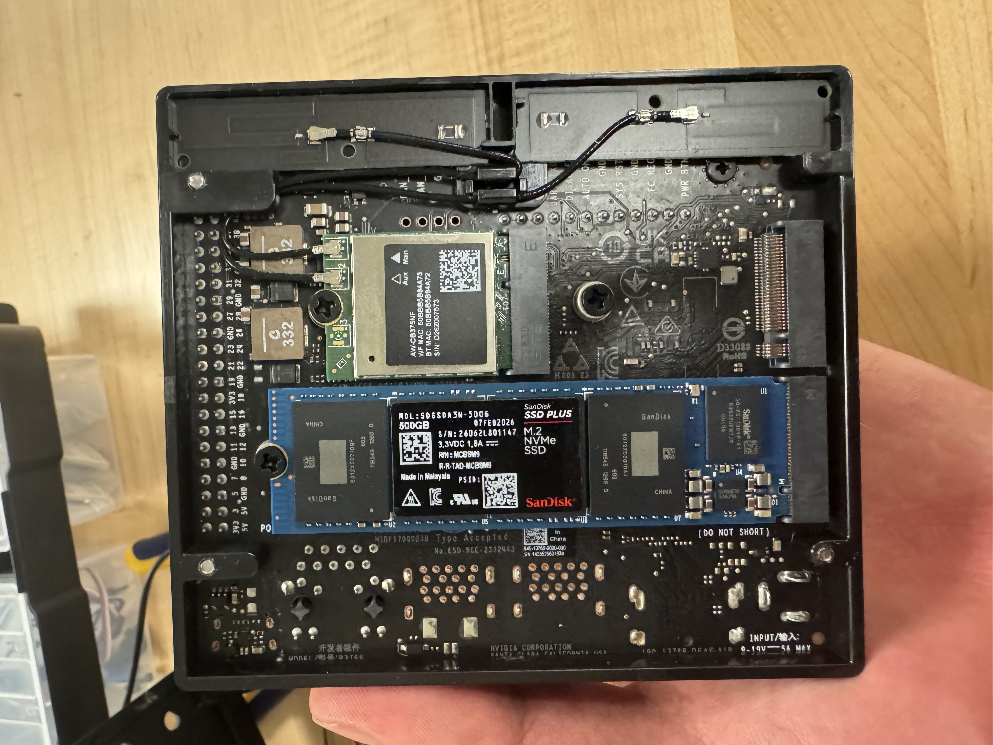 Figure 15: Screw tips marking the Jetson Orin Nano mounting hole positions.
Attach the Jetson Orin Nano to the plate using M2.5 x .45mm × 12 mm socket head cap screws at the designated mounting holes, threading the wood with the screw.
 Figure 16: Jetson Orin Nano mounted to the plate.
Step 5: Prepare the Power Board Standoffs
Screw two M3 x 8 mm female-to-female standoffs onto the bottom of the power board using M3 × 6 mm pan head screws, in the holes located on either side of the BAT and VESC terminal blocks.
Step 6: Mount the Power Board
Attach the power board to the plate as follows:
- Secure the two holes without standoffs to the Orin's 3D-printed mount using M3 x .5mm x 6mm socket head screws.
- Countersink the bottom of the plate at the standoff locations for M3 flat head screws.
- Secure the standoff side by screwing M3 x .5mm x 10mm flat head screws through the bottom of the plate into the standoffs.
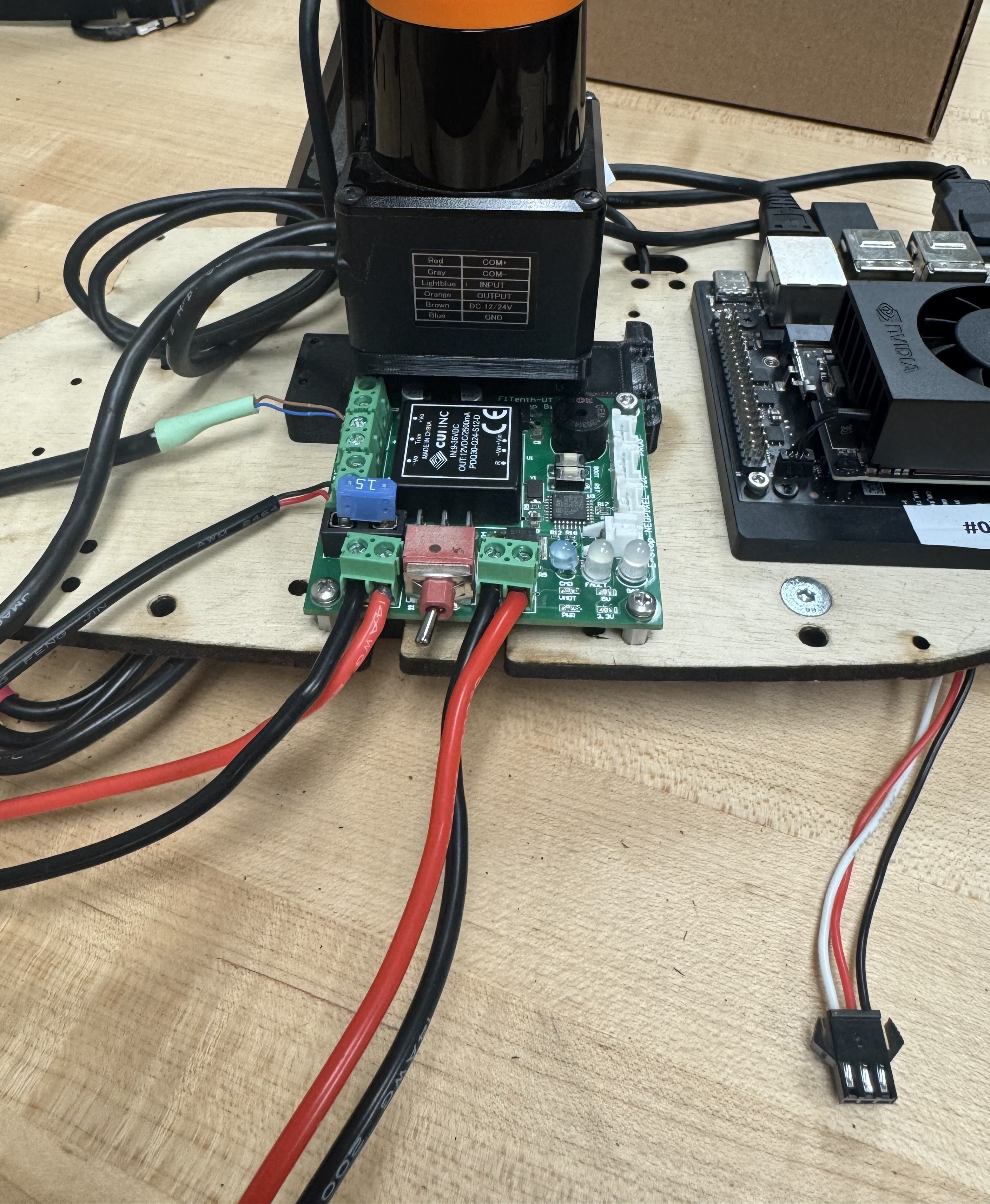 Figure 17: Power board mounted to the plate.
Step 7: Mount the IMU
Solder the header pins onto the IMU before mounting. Attach the MPU6050 IMU to the last two holes of the 3D-printed LiDAR mount (nearest to the Jetson) using M3 × 4 mm flat head screws. Connect the IMU to the Jetson Orin Nano using female-to-female jumper wires with the following pin mapping:
| IMU Pin | Jetson Pin Number |
|---|---|
| VCC | 1 |
| GND | 3 |
| SCL | 5 |
| SDA | 6 |
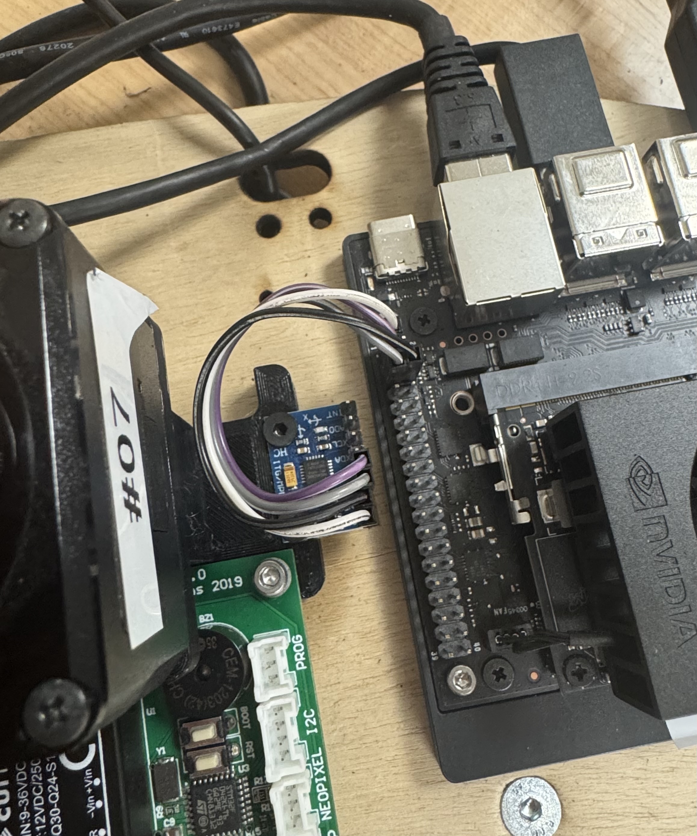 Figure 18: IMU mounted and wired to the Jetson.
Step 8: Mount the USB Hub
Place the USB hub in the gap on the opposite side of the LiDAR mount. Secure it to the plate using the two 3D-printed clamps, screwing the clamps into the plate with M3 x .5mm x 10mm flat head screws.
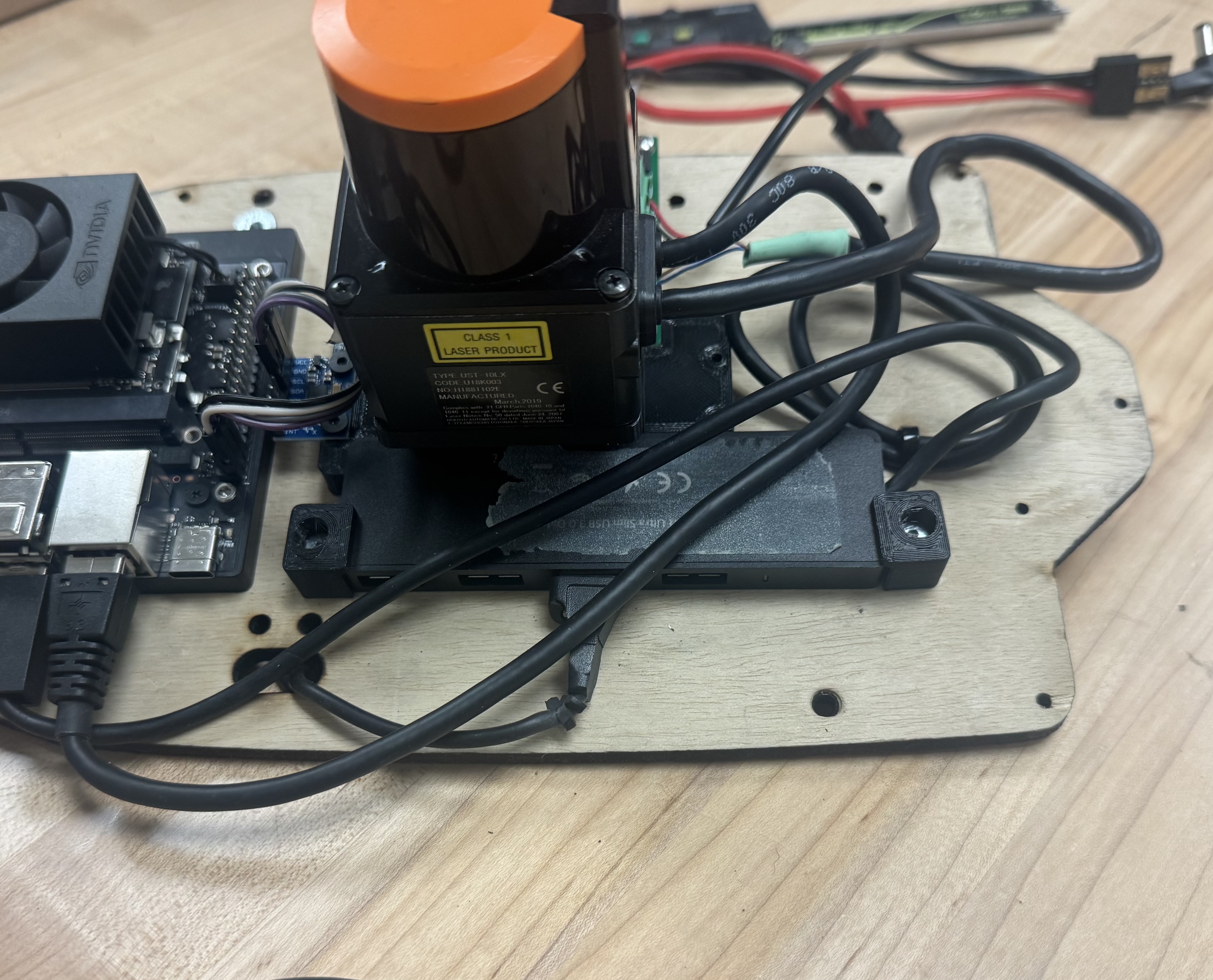 Figure 19: USB hub secured to the plate with 3D-printed clamps.
Connecting
With all components mounted, make the following connections:
- Connect the VESC TRX connector from the power board to the TRX connector coming from the VESC on the underside of the plate.
- Connect the Jetson barrel jack from the power board to the Orin Nano's power input.
- Connect the LiDAR Ethernet cable to the Jetson Orin Nano's Ethernet port.
- Connect the USB hub to the Jetson using the hub's attached USB cable.
- Connect the DisplayPort end of the DP to HDMI cable to the Jetson.
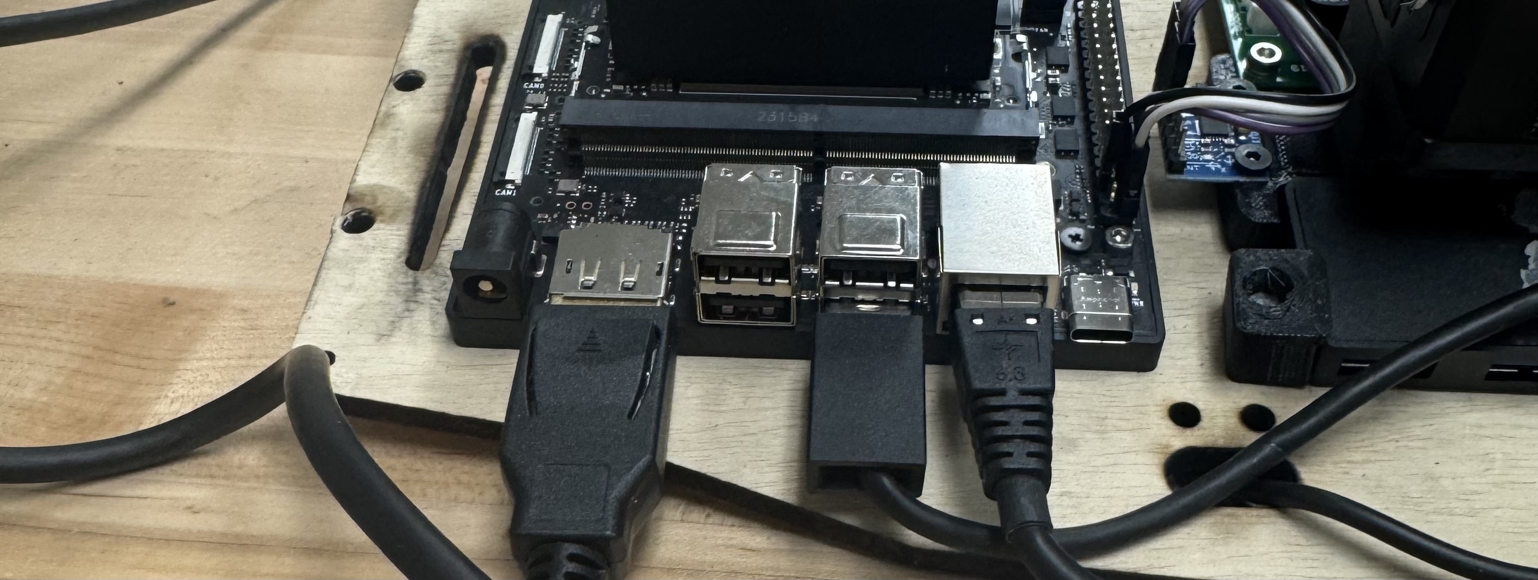 Figure 20: All cable connections on the Jetson side of the plate.
Camera
Step 1: Attach the Camera to the Mount
Secure the Raspberry Pi camera to the flat side of the 3D-printed camera mount using M2 × 4 mm flat head screws.
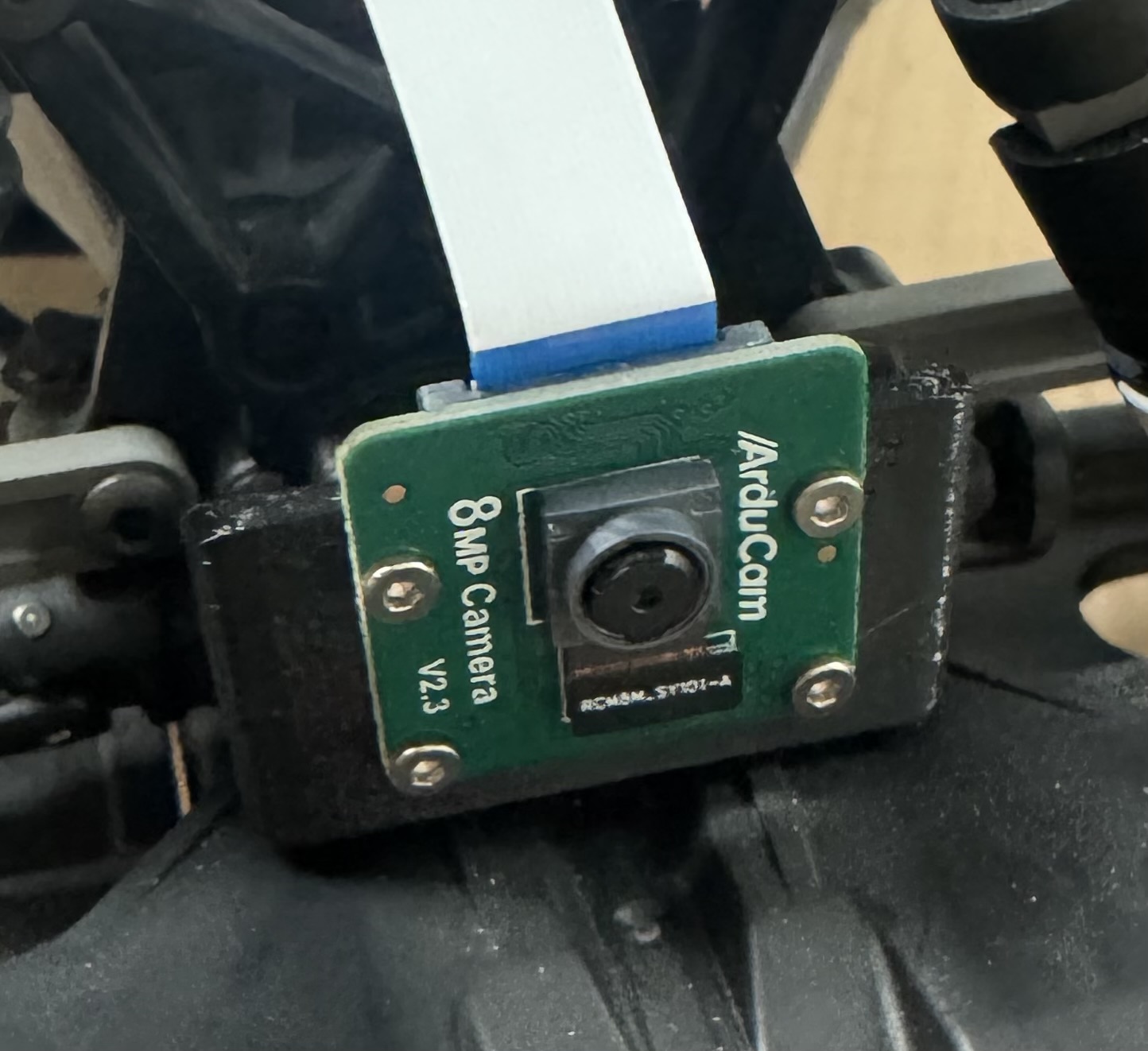 Figure 21: Camera attached to the 3D-printed mount.
Step 2: Mount to the Car
Attach the camera mount to the front of the chassis using M3 × 15 mm pan head screws.
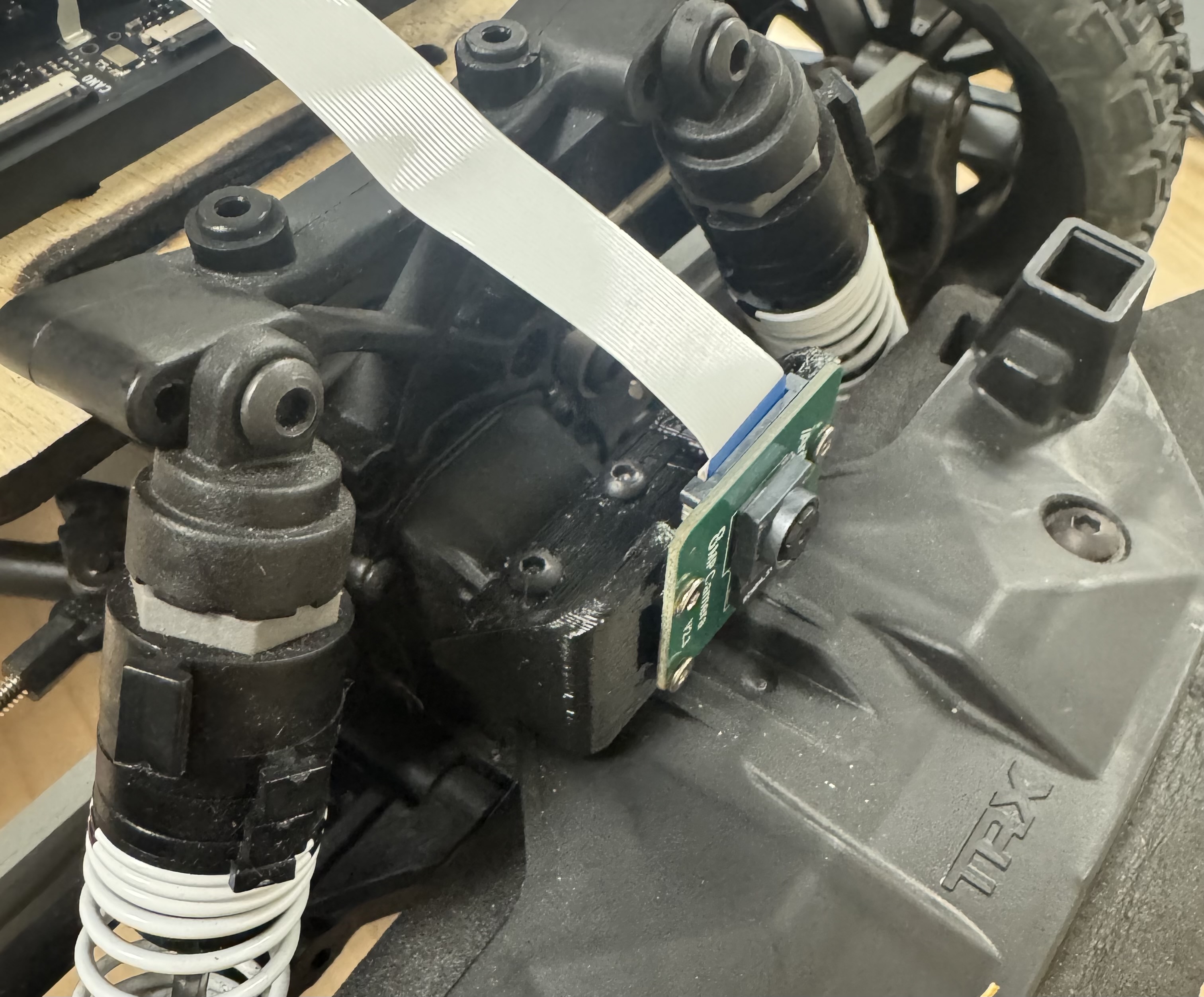 Figure 22: Camera mount secured to the front of the chassis.
Step 3: Install the Cover
Slide the 3D-printed cover over the camera mount.
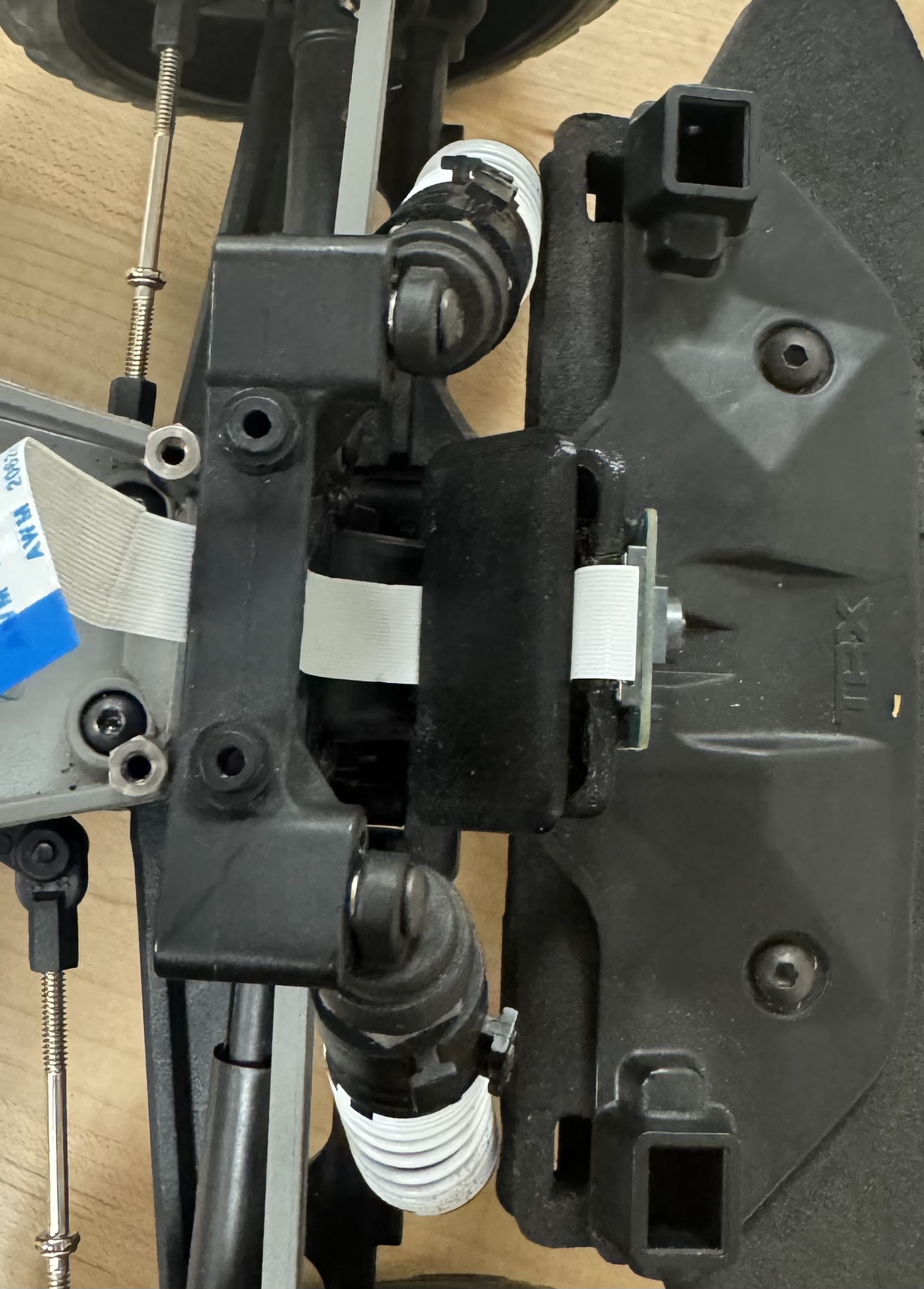 Figure 23: Camera cover installed.
Mounting Plate
Step 1: Attach the Plate to the Chassis
Countersink the mounting plate on the opposite side of where the standoffs from the car align. Screw the plate to the standoffs of the car using M3 × 8 mm flat head screws.
Step 2: Route the Battery Cable
Cross the TRX connector from the BAT terminal on the power board over to the opposite side of the plate, routing it underneath. The battery will sit in the empty gap in the chassis.
Step 3: Connect the Motor
Connect the gold bullet connectors from the VESC to the BLDC motor leads. Connect the JST-SM 3-pin connector from the VESC to the servo on the chassis.
Step 4: Connect the Camera Cable
Connect the Raspberry Pi camera ribbon cable to the CAM0 port on the Jetson, sliding the cable through the slit in the mounting plate.
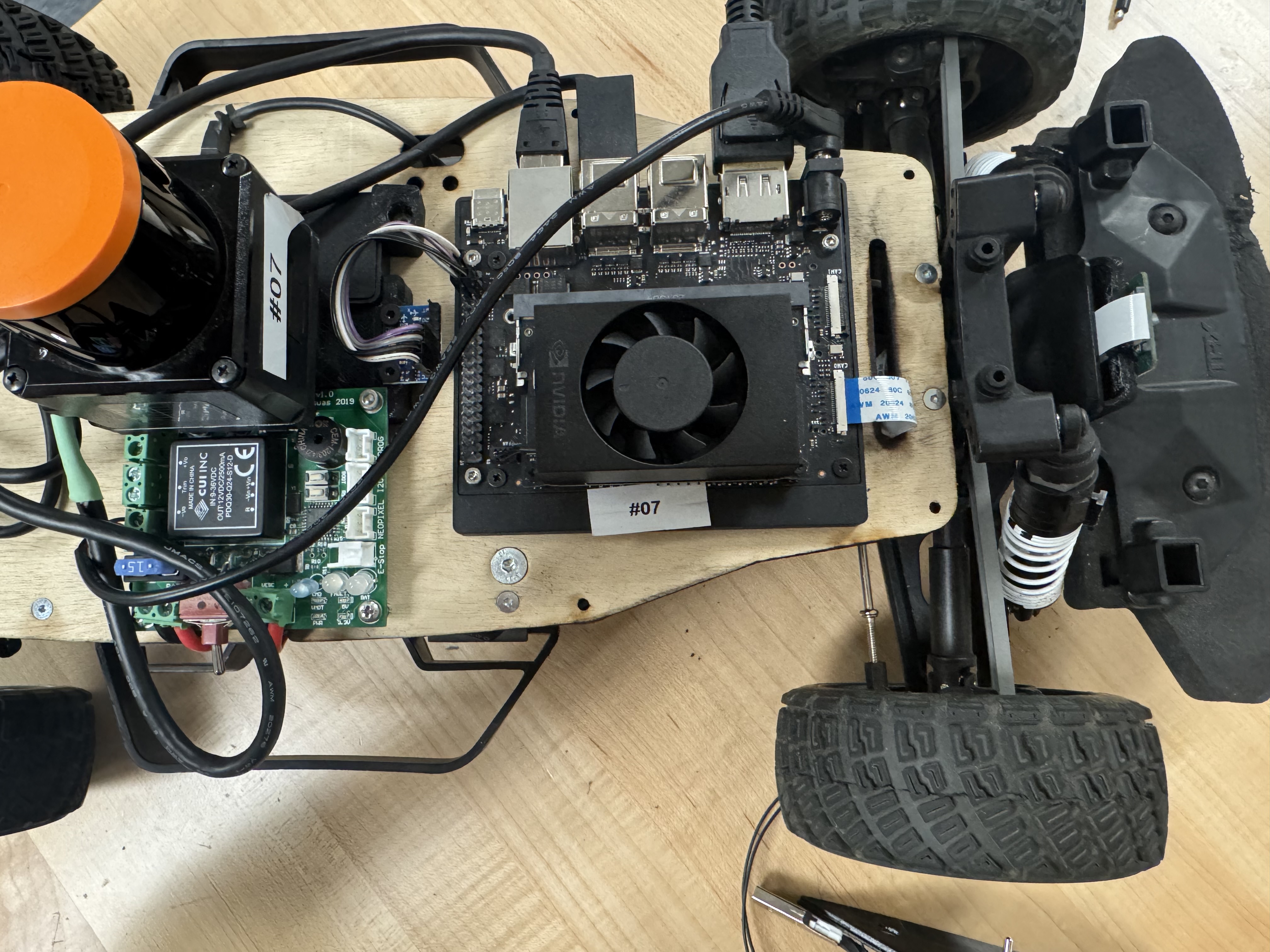 Figure 24: Camera ribbon cable routed through the plate and connected to the Jetson.
Screen
Step 1: Prepare the Screen Mount
TODO: Solder the switch and estop cable and attach it to the 3D-printed screen mount.
Step 2: Install Mounting Screws
Thread two M3 x .5mm x 8mm pan head screws into the screen's mounting holes, leaving the threads extending outward as shown below.
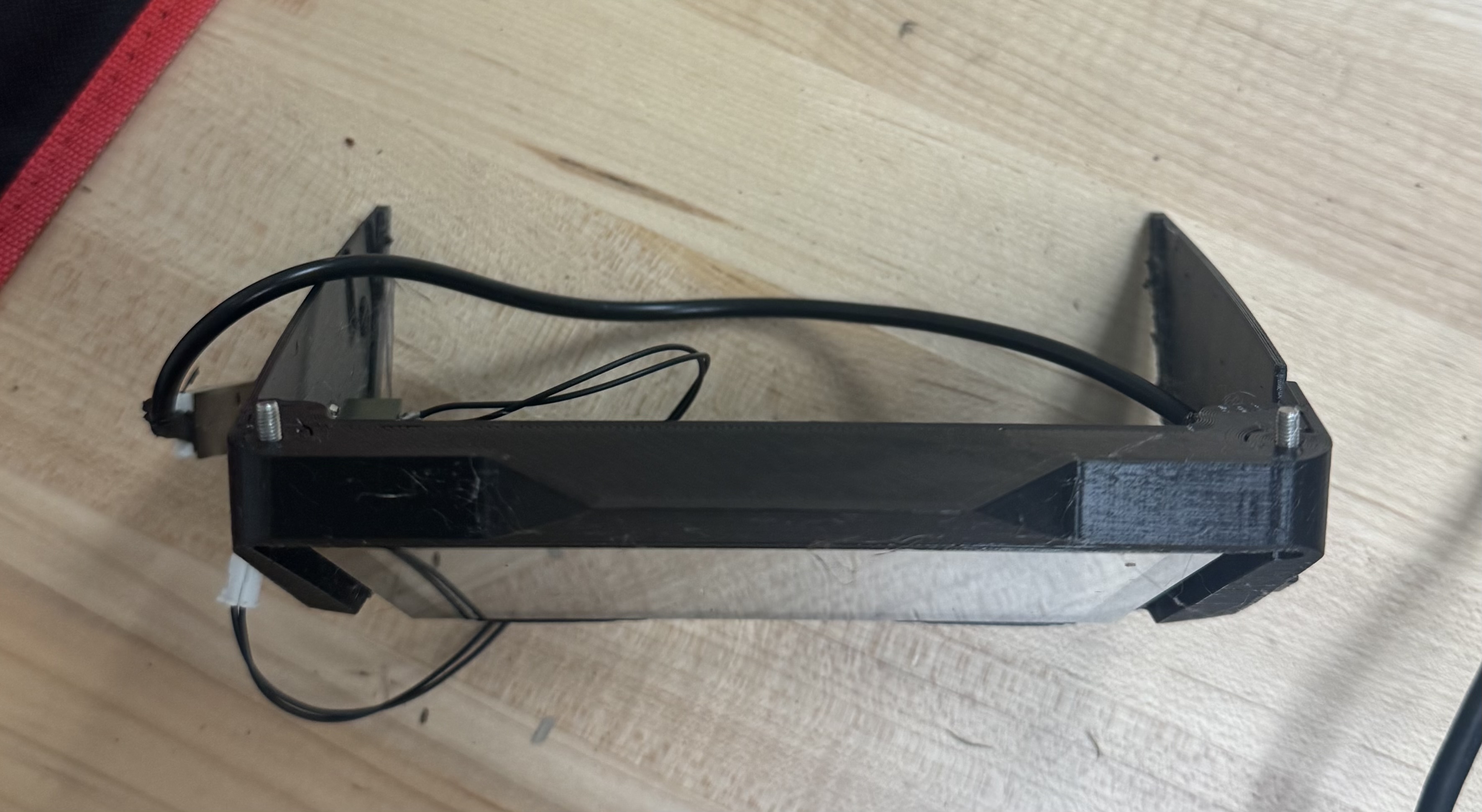 Figure 25: M3 mounting screws installed in the screen.
Step 3: Connect the Screen USB
Connect the Micro-USB end of a USB cable to the screen.
Step 4: Attach the Screen to the Mount
Place the screen on the 3D-printed mount, aligning the ports. Secure with the M3 x 0.5mm x 8mm pan head screws.
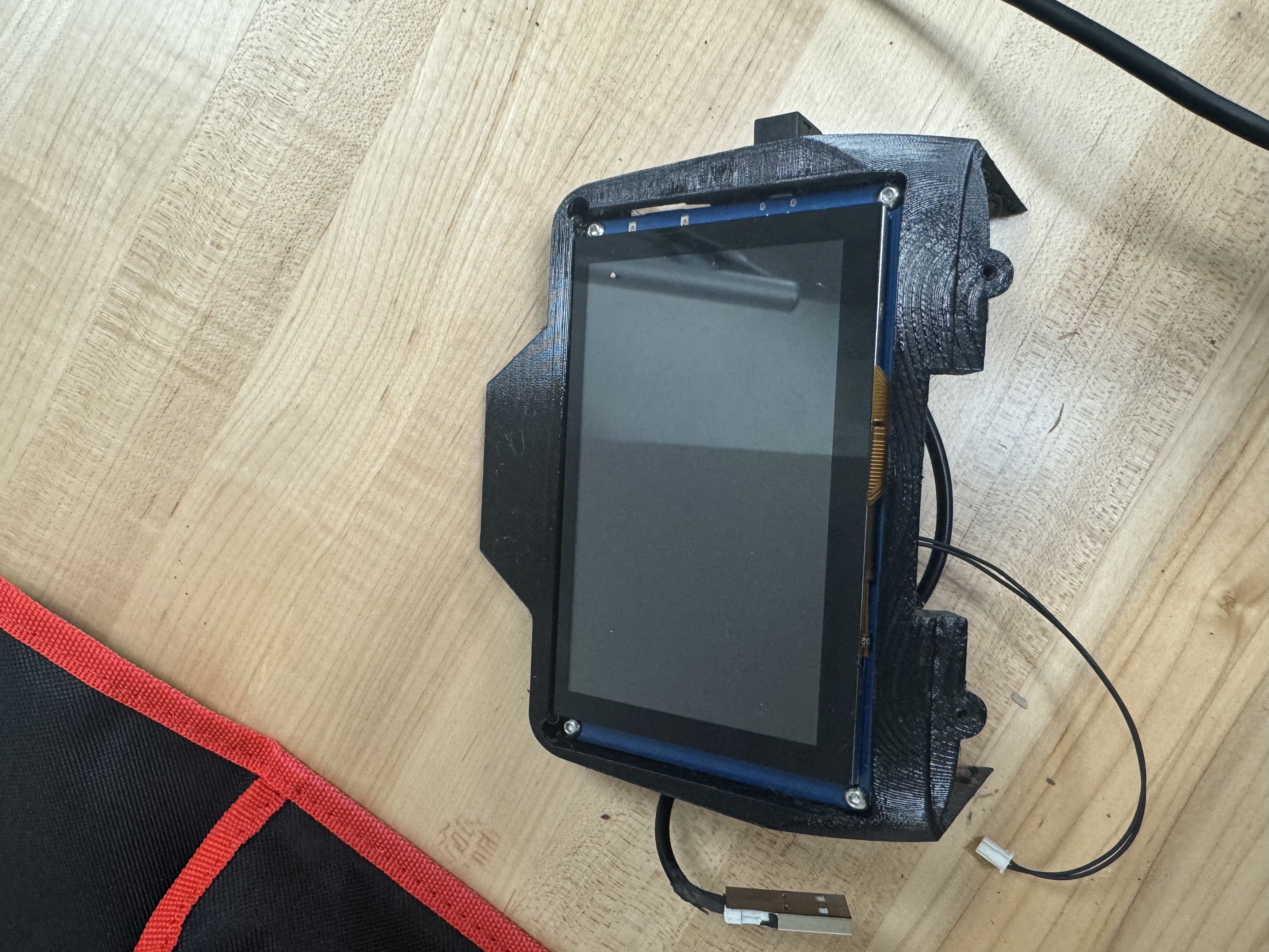 Figure 26: Screen secured to the mount.
Step 5: Final Screen Installation
Connect the USB cable from the screen to the USB hub on the plate. Place the screen assembly in its designated position on the mounting plate. Slide the BAT and VESC cables through the bottom of the plate using the slit, and slide the power switch into the hole on the screen mount. Secure the screen mount to the plate using the screws from Step 2.
Step 6: Final Connections
Connect the HDMI end of the DP to HDMI cable to the screen. Connect the pin from the screen switch cable to the E-Stop terminal on the power board.
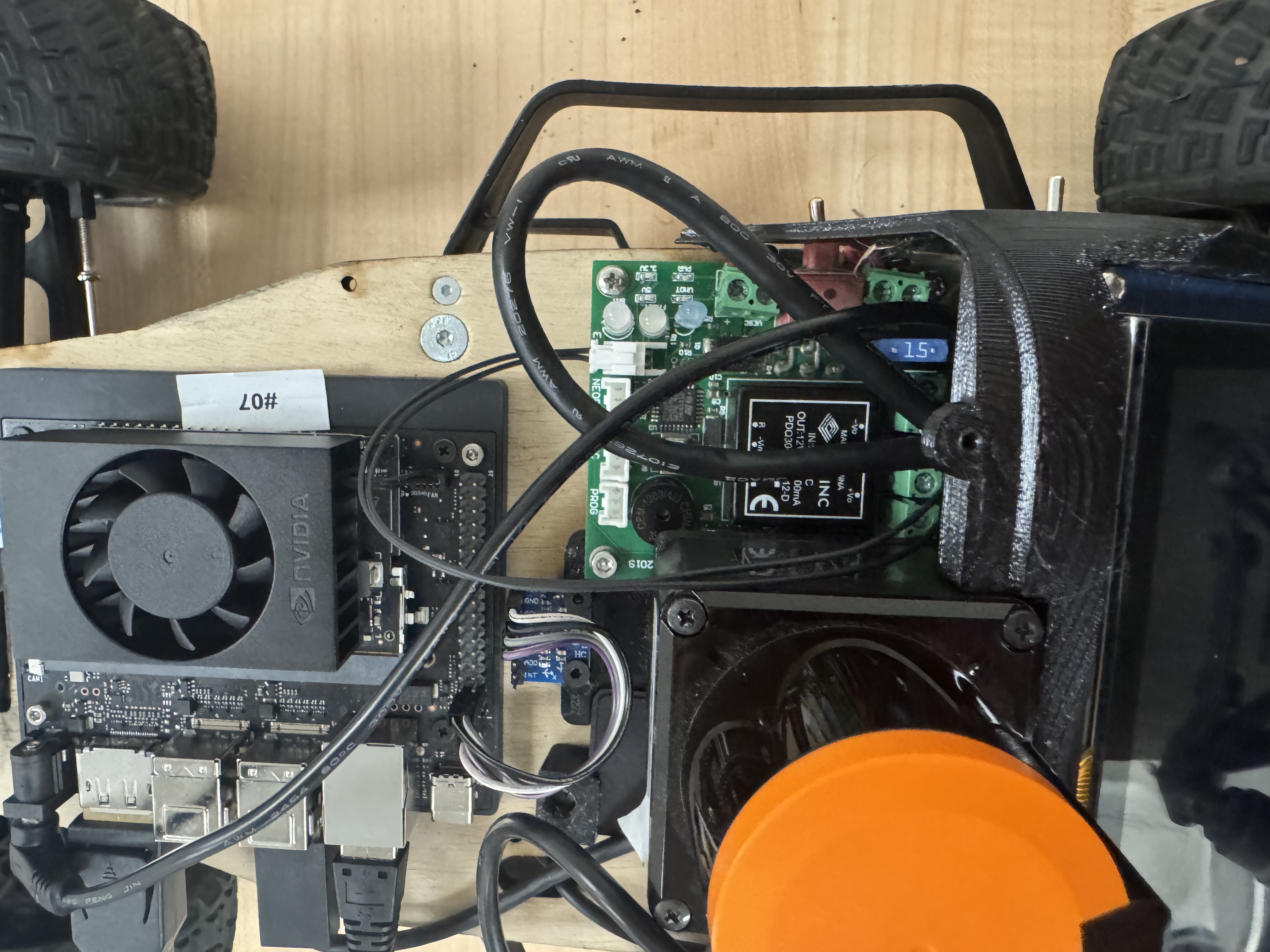 Figure 27: Power switch connected to the E-Stop terminal on the power board.
Completed Assembly
Your fully assembled RoboRacer platform should now look like the image below. Verify all connections before powering on the vehicle for the first time.
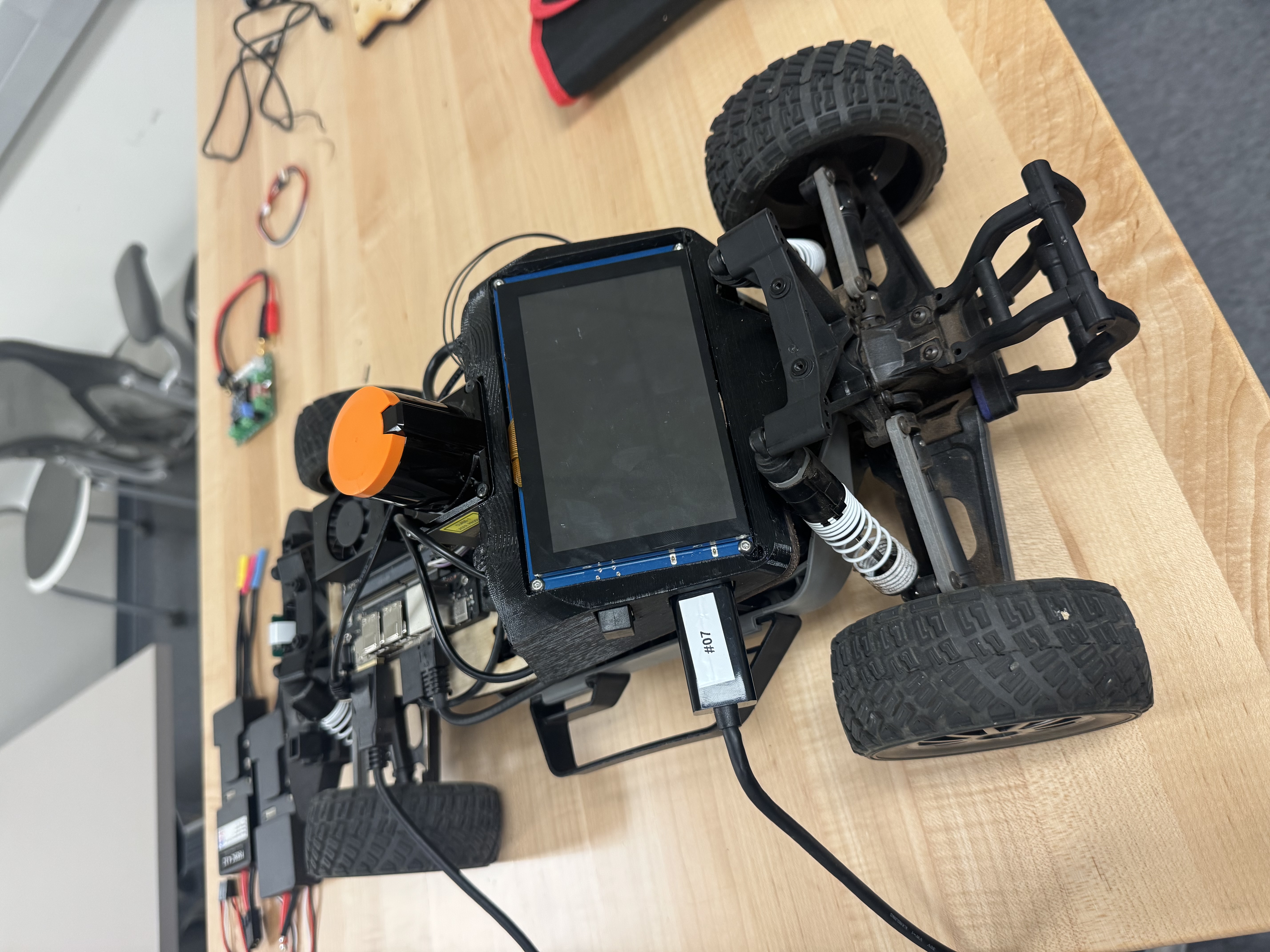 Figure 28: Fully assembled RoboRacer platform.
Verification Checklist
Before powering on the platform, verify the following:
- All screws are tightened and no components are loose.
- The VESC TRX and bullet connectors are firmly seated with correct polarity.
- The Jetson barrel jack is connected and secure.
- The LiDAR Ethernet cable is plugged in.
- The IMU jumper wires are connected to the correct Jetson pins.
- The camera ribbon cable is properly seated in the CAM0 port.
- The DP to HDMI cable connects the Jetson to the screen.
- The USB hub is connected to the Jetson and the screen.
- The E-Stop switch is wired to the power board.
- The battery TRX cable is routed safely and accessible.